Swash plate type valve distributing high-pressure pure water plunger pump
A swash plate type, high-pressure technology, which is applied to variable capacity pump parts, parts of pumping devices for elastic fluids, pumps, etc., can solve the problem of large cylinder running swing, large leakage of pure water plunger pumps, etc. problems, to achieve smooth operation, reduce wear resistance requirements, good sealing performance and suction performance
- Summary
- Abstract
- Description
- Claims
- Application Information
AI Technical Summary
Problems solved by technology
Method used
Image


Examples
Embodiment 1
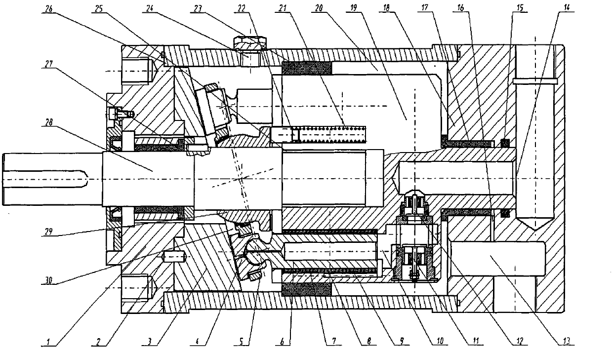
[0029] Such as figure 1 As shown, the present invention includes a pump body 26, a main shaft 28 arranged in the pump body 26, and a front end cover 1 installed on the main shaft 28 from left to right, a swash plate-slider mechanism, a ball joint 29, a plunger- Cylinder mechanism, distribution valve and rear end cover 18. The front end cover 1 and the rear end cover 18 are respectively fixed on the left and right sides of the pump body 26 . The swash plate-slider mechanism includes a swash plate 3 , a return plate 5 , and an odd number of slide shoes 4 . Wherein, the left side of the swash plate 3 is connected with the front end cover 1 through the pin 2, and the right side surface is an inclined plane. An odd number of sliding shoes 4 are evenly arranged in the return disk 5 along the circumferential direction, and the sliding shoes 4 are hinged to the plunger 6 .
[0030] The plunger-cylinder mechanism includes a cylinder 19 and a plunger 6 , the inner hole of the cylinde...
Embodiment 2
[0044] The structure in this embodiment is basically the same as that in Embodiment 1, the only difference is that the water inlet form of the suction valve is different: in this embodiment, the suction valve 11 and the pressure discharge valve 12 are arranged at the tail of the cylinder body 19 along the radial direction of the main shaft , but the valve port 31 of the suction valve 11 opens in the axial direction. Compared with the distribution valve structure of the first embodiment, when the low-pressure water enters the common cavity 32 of the distribution valve from the valve port 31 of the suction valve 11, it is not affected by the centrifugal force of the rotation of the cylinder body 19, and the water absorption effect is better; compared with the distribution valve of the third embodiment structure, the cylinder body 19 has a smaller volume.
Embodiment 3
[0046] The structure in this embodiment is basically the same as that in Embodiment 1, the only difference is that the arrangement of the suction valves is different: in this embodiment, the extrusion valve 12 is radially arranged, the suction valve 11 is axially arranged at the tail of the cylinder 19, and the suction The valve port 31 of the valve 11 is open in the axial direction, and the valve port 31 communicates directly with the water suction port 13 . Compared with Embodiment 1, when the low-pressure water enters the common chamber 38 of the distribution valve from the valve port 31 of the suction valve 11, it is not affected by the centrifugal force of the rotation of the cylinder body 19, and the water absorption effect is better.
PUM
 Abstract
Description
Claims
Application Information