
Light-emitting diode lamp bulb capable of performing forced convection and cooling

A technology of LED bulbs and forced convection, which is applied to lighting and heating equipment, components of lighting devices, emergency protection devices for automatic disconnection, etc. Large and other problems, to achieve the effect of broad promotion and application prospects, long overall service life, and compact overall structure

Inactive Publication Date: 2011-01-19
江苏森隆机电有限公司
View PDF6 Cites 9 Cited by
  • Summary
  • Abstract
  • Description
  • Claims
  • Application Information

AI Technical Summary

Problems solved by technology

However, the existing household LED lighting lamps all adopt a passive heat dissipation method. Due to the large volume of the heat sink, the volume of the lamp is also increased, which brings inconvenience to the use of the lamp. At the same time, due to the heat dissipation of the existing lamp during use The air flow around the chip is not good, resulting in poor heat dissipation, and the LED is an electronic component. The high operating temperature directly shortens the service life of the LED.
Due to the large heat sink and short service life, the cost of lighting remains high, which is not conducive to the popularization of LED lighting fixtures

Method used


Image

  • Light-emitting diode lamp bulb capable of performing forced convection and cooling
  • Light-emitting diode lamp bulb capable of performing forced convection and cooling
  • Light-emitting diode lamp bulb capable of performing forced convection and cooling

Examples


Embodiment Construction

[0013] The LED light bulb for forced convection heat dissipation of the present invention will be further described in detail below in conjunction with the accompanying drawings and specific embodiments.

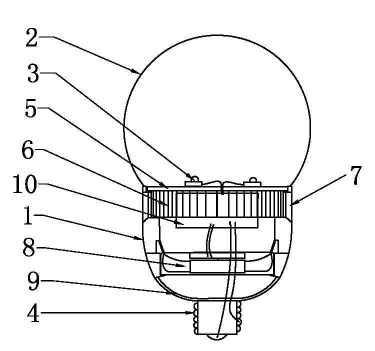
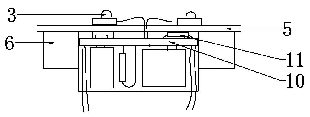
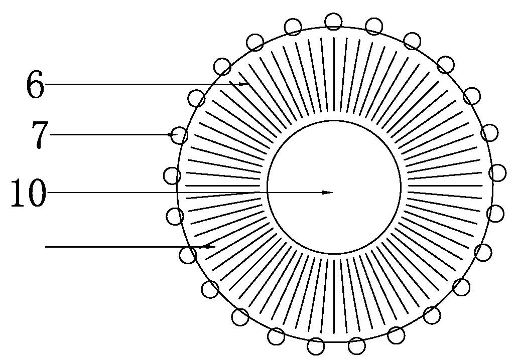
[0014] As shown in the figure, the LED light bulb with forced convection heat dissipation of the present invention includes a housing 1, a lampshade 2 is arranged on the upper end of the housing, an LED lamp bead 3 is installed in the lampshade, and a lamp cap 4 is arranged at the center of the lower end of the housing; the upper end of the inner cavity of the housing A lamp bead substrate 5 is provided, and the LED lamp beads 3 in the lampshade are installed on the upper surface of the lamp bead substrate 5, and a plurality of heat sinks 6 are arranged on the lower surface of the lamp bead substrate 5, and the housing wall plate around the heat sink is provided with An air outlet grille 7; an axial flow fan 8 is installed in the middle of the inner cavity of the housing, and...


PUM


Abstract

The invention relates to a lighting device, in particular to a light-emitting diode (LED) lamp bulb capable of performing forced convection and cooling. The LED lamp bulb comprises a casing, wherein the upper end of the casing is provided with a lampshade; LED lamp beads are arranged in the lampshade, the center of the lower end of the casing is provided with a lamp holder; the upper end of the cavity of the casing is provided with a lamp bead base plate, the LED lamp beads in the lampshade are arranged on the upper surface of the lamp bead base plate, the lower surface of the lamp bead base plate is provided with a plurality of cooling fins, the casing wall panel on the periphery of the cooling fins is provided with a gas outlet grid; the middle of the cavity of the casing is provided with an axial fan, and the lower end surface of the casing is provided with a gas inlet grid. The LED lamp bulb has good heat dissipation effect, high safety factor and long overall service life, the maintenance frequency can be lowered and the volume of the cooling fins can be reduced. Meanwhile, the distribution of the cooling fins is rational and the overall structure of the lamp bulb is compact, thus the style and size of the LED lamp bulb are similar to that of the common lamp bulb, the replacement between the LED lamp bulb and the common lamp bulb can be realized and the LED lamp bulb is extremely convenient to use. Therefore, the LED lamp bulb has wide popularization and application prospects.

Description

technical field [0001] The invention relates to an illuminating device, more specifically to an LED light bulb with forced convection and heat dissipation. Background technique [0002] The current LED lighting fixtures have the advantages of low power consumption, high brightness, and cold light source, and are lighting methods with good development prospects. However, the existing household LED lighting lamps all adopt a passive heat dissipation method. Due to the large volume of the heat sink, the volume of the lamp is also increased, which brings inconvenience to the use of the lamp. At the same time, due to the heat dissipation of the existing lamp The air flow around the chip is not good, resulting in poor heat dissipation, and the LED is an electronic component. The high operating temperature directly shortens the service life of the LED. Due to the excessively large heat sink and short service life, the cost of lighting remains high, which is not conducive to the po...

Claims


Application Information

Patent Timeline
Patent Type & Authority Applications(China)
IPC IPC(8): F21S2/00F21V29/02F21V17/00H02H5/04F21Y101/02F21V29/50F21V29/67
Inventor 许严
Owner 江苏森隆机电有限公司
Learn More