
Movement comparison-based dual-frequency laser interferometer signal high multiple-frequency subdivision system

A dual-frequency laser interference and signal technology, applied in transmission systems, electromagnetic wave transmission systems, instruments, etc., can solve problems such as limitations, limitations, and extremely limited improvement in measurement accuracy, achieve high stability and reliability, and improve subdivision The effect of precision

Inactive Publication Date: 2011-01-19
XI AN JIAOTONG UNIV
View PDF5 Cites 10 Cited by
  • Summary
  • Abstract
  • Description
  • Claims
  • Application Information

AI Technical Summary

Problems solved by technology

The principle of the subdivision method based on phase-locked frequency multiplication is that the measurement channel and the reference channel signal are phase-locked and frequency-multiplied at the same time. After digital demodulation, a frequency-multiplied pulse related to displacement is obtained. The pulse passes through the counter and buffer, and then processed by the CPU. The displacement information is obtained, and the characteristic is that the demodulated pulse can also directly enter the motion control to achieve high-precision positioning control, but the frequency tracking bandwidth of the multiplier phase-locked is limited, and the control of digital demodulation is limited by high-frequency work
However, the digital phase detection subdivision method based on pulse filling is also limited by many factors, so the improvement of measurement accuracy is extremely limited

Method used


Image

  • Movement comparison-based dual-frequency laser interferometer signal high multiple-frequency subdivision system
  • Movement comparison-based dual-frequency laser interferometer signal high multiple-frequency subdivision system
  • Movement comparison-based dual-frequency laser interferometer signal high multiple-frequency subdivision system

Examples


Embodiment Construction

[0017] The present invention is described in further detail below in conjunction with accompanying drawing:

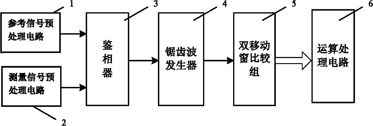
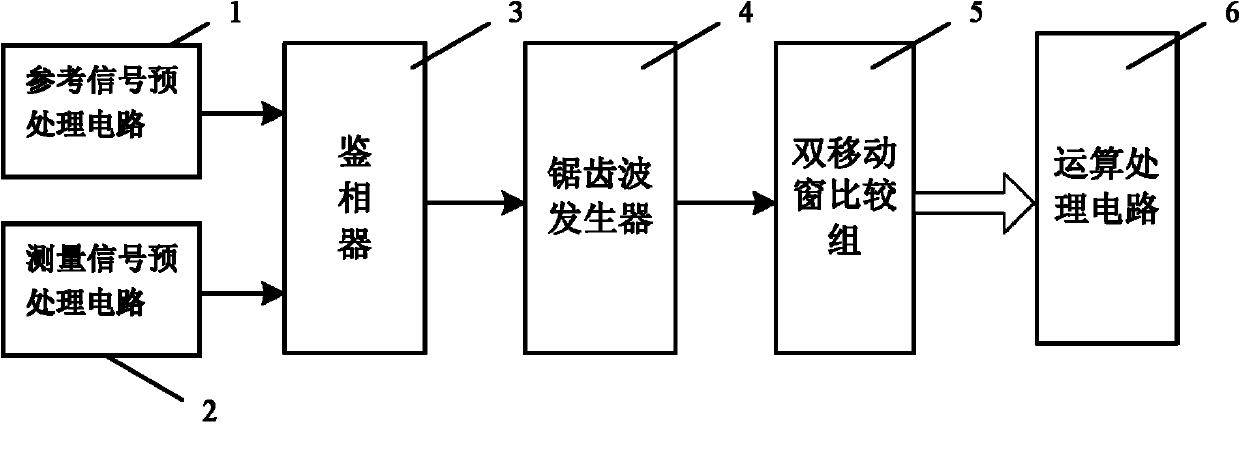
[0018] see figure 1 , the dual-frequency laser interferometer signal high-frequency subdivision system based on mobile comparison of the present invention includes a reference signal preprocessing circuit 1, a measurement signal preprocessing circuit 2, a phase detector 3, a sawtooth wave generator 4, and a double moving window comparison Group 5 and arithmetic processing circuit 6. Wherein the signal output terminals of the reference signal preprocessing circuit 1 and the measurement signal preprocessing circuit 2 are respectively connected with the signal input terminals of the phase detector 3, the phase detector 3, the sawtooth wave generator 4, the double moving window comparison group 5 and the operation processing The circuits 6 are connected in sequence. The specific signal processing and flow direction between the above parts are as follows:

[0019] The me...


PUM


Abstract

The invention discloses a movement comparison-based dual-frequency laser interferometer signal high multiple-frequency subdivision system. The system comprises a reference signal pre-processing circuit 1, a measurement signal pre-processing circuit 2, a phase discriminator 3, a sawtooth generator 4, a dual mobile window comparable group 5 and an operation processing circuit 6, wherein the signal output ends of the reference signal pre-processing circuit 1 and the measurement signal pre-processing circuit 2 are connected with the signal input end of the phase discriminator 3 respectively; and the phase discriminator 3, the sawtooth generator 4, the dual mobile window comparable group 5 and the operation processing circuit 6 are connected with one another sequentially. In the system, high multiple-frequency subdivided integer and decimal signals are generated by using the dual mobile window comparable group, data is processed by an operation circuit, the period and phase information of the dual-frequency laser interferometer signal can be accurately measured with high resolution, and the measurement accuracy of a dual-frequency laser interferometer measurement system is improved considerably.

Description

technical field [0001] The invention belongs to the technical field of photoelectric detection, and relates to a laser interferometer phase subdivision method, in particular to a high-magnification subdivision system for the phase of a dual-frequency laser interferometer. The system can be widely used in ultra-large-scale integrated circuit processing equipment, precision On-line in-position measurement, error correction and control of machine tools, etc. Background technique [0002] Dual-frequency laser interferometer is the most authoritative length measuring instrument in the industry, and is widely used in on-line in-situ measurement, error correction and control of various precision machine tools and large-scale integrated circuit processing equipment. Theoretically, if the output signal of the dual-frequency laser interferometer is not subdivided, the final measurement accuracy can only reach half of the wavelength of the laser light source. With the development of n...

Claims


Application Information

Patent Timeline
IPC IPC(8): G01B9/02
CPCG01B9/02007H04B10/00G02B6/12007
Inventor 邵伟郭俊杰周阿维王昭张涛
Owner XI AN JIAOTONG UNIV
Learn More