Method for calibrating three-dimensional imaging system

A technology of three-dimensional imaging and calibration method, which is applied in the direction of measuring devices, instruments, and optical devices, etc., can solve the problems of cumbersome calibration process, low parameter accuracy, and unsuitable use, and achieve saving storage space, high accuracy, and cost cheap effect

Inactive Publication Date: 2011-01-19
众趣(北京)科技有限公司
View PDF3 Cites 36 Cited by
  • Summary
  • Abstract
  • Description
  • Claims
  • Application Information

AI Technical Summary

Problems solved by technology

Therefore, the process of model-based calibration technology is cumbersome, and the accuracy of the obtained parameters is not high; polynomial-based calibration technology needs a look-up table to establish the relationship between the depth and phase of each pixel
In addition, most of the two methods require precise two-dimensional or

Method used


Image

  • Method for calibrating three-dimensional imaging system
  • Method for calibrating three-dimensional imaging system
  • Method for calibrating three-dimensional imaging system

Examples


Embodiment Construction

[0038] Further describe the present invention below in conjunction with embodiment and accompanying drawing thereof, but the scope of protection of the claims of the present invention application is not limited by embodiment.

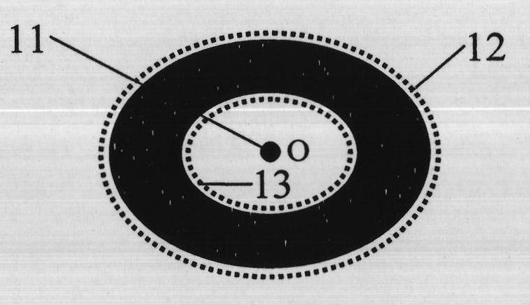
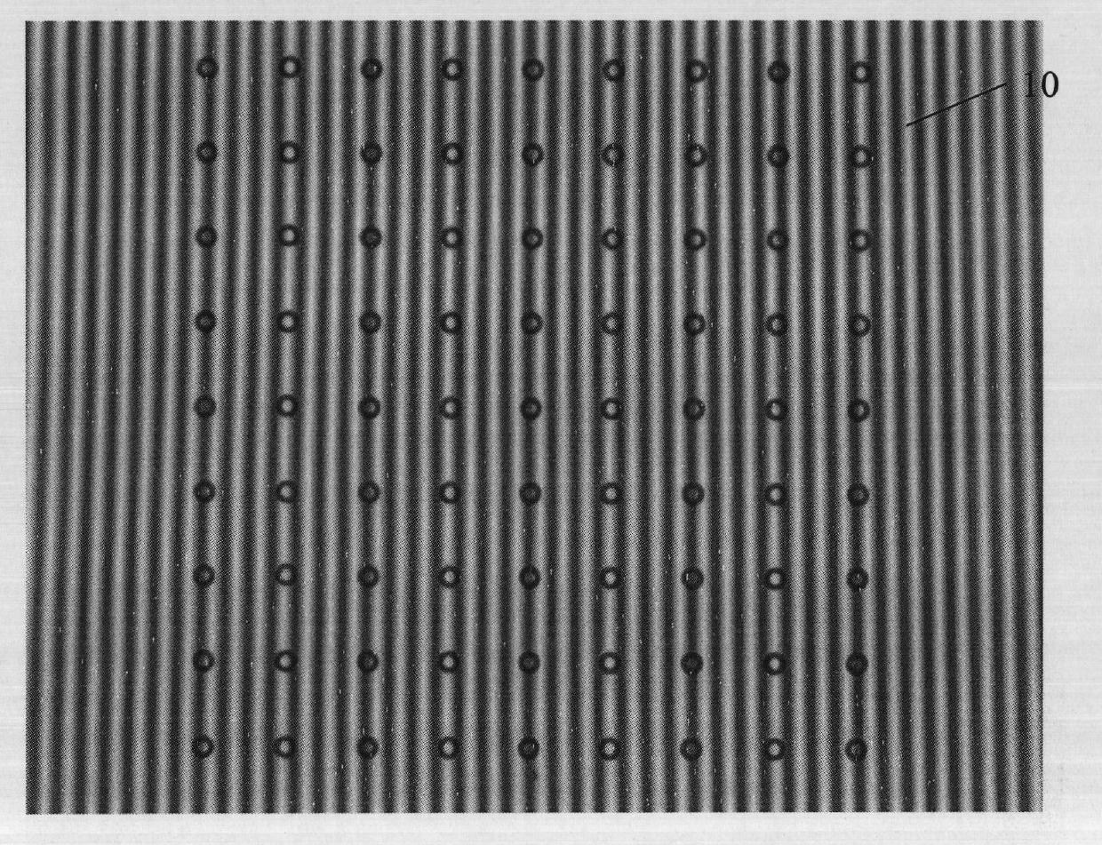
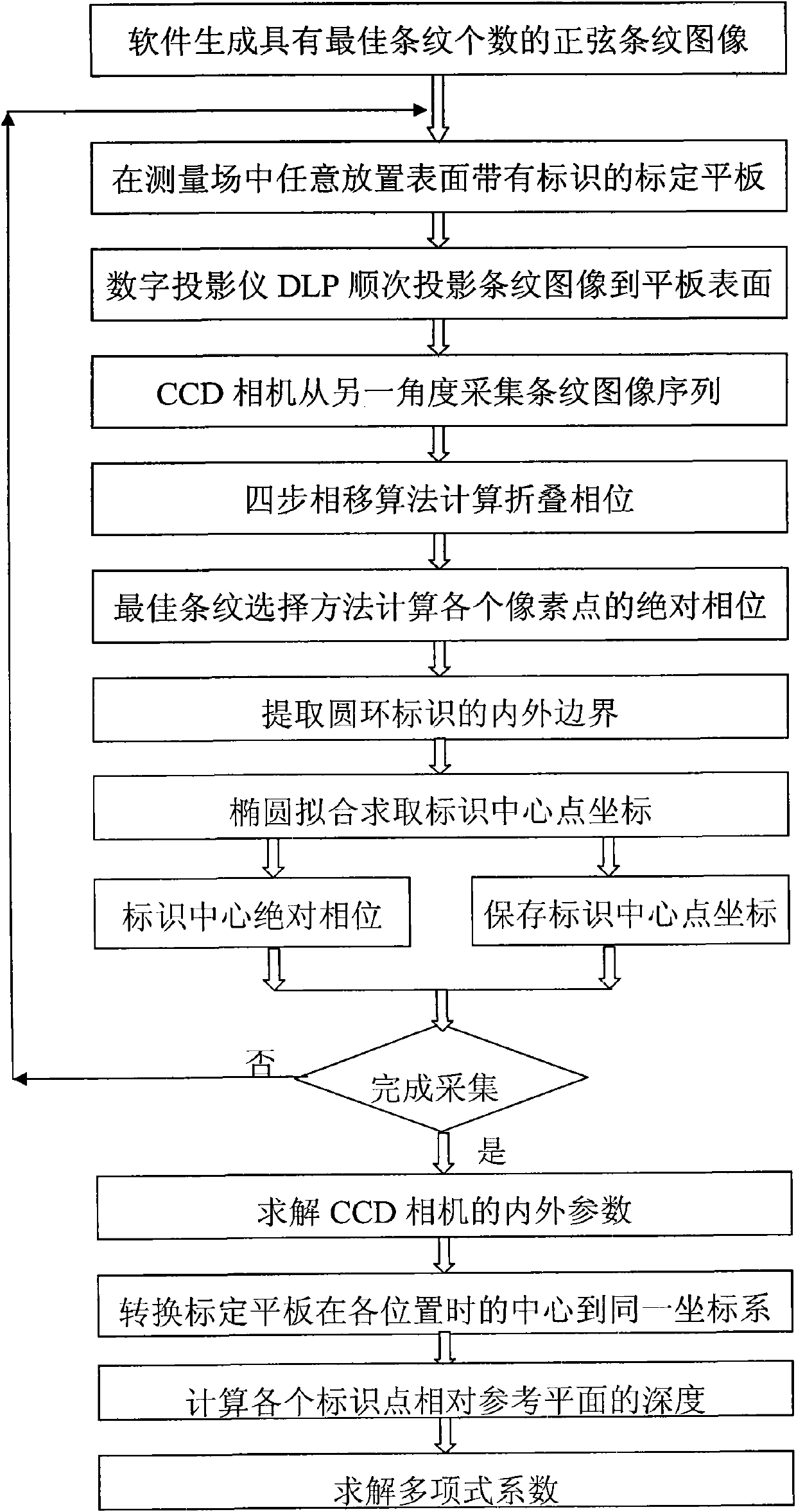
[0039] The calibration method of the three-dimensional imaging system designed by the present invention (abbreviation calibration method, see Figure 1-12 ), based on phase measurements, using a three-dimensional calibration structure (see figure 1 ), the equipment used mainly includes: computer 1, CCD digital camera (referred to as CCD camera) 2, DLP digital projector (referred to as DLP projector) 3, and a self-designed calibration tablet with a black ring logo on the surface (referred to as calibration tablet) 4. The computer 1 is connected with the DLP digital projector 3 through the video interface on it, and is connected with the CCD digital camera 2 through the IEEE1394 interface on it. The computer 1 is used to control the DLP projector 3 and ...


PUM


Abstract

The invention discloses a method for calibrating a three-dimensional imaging system, which comprises the following steps of: 1, designing a calibration flat plate to be white and have a diffuse reflection surface and designing black annular identifiers in a square matrix arrangement mode on the calibration flat plate simultaneously, wherein the center distance between adjacent identifiers is equal; 2, placing the calibration flat plate at different positions in a measurement field, projecting non-uniform sinusoidal grating stripes with the optimal number of stripes at each placement position onto the surface of the calibration flat plate, and acquiring and calculating the absolute phase of each white pixel point inside the black annular identifiers; 3, extracting the central point position of each identifier from a corresponding absolute phase diagram to solve the relative depths of the identifiers when the calibration flat plate is at each placement position; 4, establishing a high-order polynomial (A) to express the relationship between the absolute phases and the relative depths; and 5, converting the absolute phases into actual depth data by using the calibrated polynomial coefficients so as to finish the calibration of the three-dimensional imaging system.

Description

technical field [0001] The invention relates to a three-dimensional imaging system calibration technology, in particular to a three-dimensional imaging system calibration method based on non-uniform fringe projection technology to measure the surface phase of an object and establish the relationship between absolute phase and depth. Background technique [0002] Existing 3D imaging system calibration methods either rely on precisely moving and positioned plates to establish the relationship between phase and depth, which takes a long time to calibrate and is limited to a laboratory environment; or rely on calculating the internal and external parameters of the imaging unit and projection unit and Its relative positional relationship, this method is difficult to implement, and the obtained parameters are not accurate, so it is impossible to obtain high-precision three-dimensional shape data. Within the scope of the applicant's search, the calibration method of the 3D imaging ...

Claims


Application Information

Patent Timeline
IPC IPC(8): G01B11/25
Inventor 张宗华
Owner 众趣(北京)科技有限公司
Why Eureka
Try Eureka