
Simple structure for verifying optical gyroscopic effect

An optical gyroscope and effect technology, applied to measuring devices, instruments, etc., can solve problems such as difficult integration, inconvenient measurement, and large influence of changes, and achieve the effect of improving sensitivity and resolution

Inactive Publication Date: 2011-01-19
ZHONGBEI UNIV
View PDF7 Cites 0 Cited by
  • Summary
  • Abstract
  • Description
  • Claims
  • Application Information

AI Technical Summary

Problems solved by technology

[0003] In order to solve the problems of inconvenient measurement of existing gyro inertial devices, difficulty in further improving sensitivity and resolution, high cost, great influence by changes in environmental conditions such as temperature, and difficulty in integration, the present invention provides a simple method for verifying the optical gyro effect. structure

Method used


Image

  • Simple structure for verifying optical gyroscopic effect
  • Simple structure for verifying optical gyroscopic effect
  • Simple structure for verifying optical gyroscopic effect

Examples


Embodiment Construction

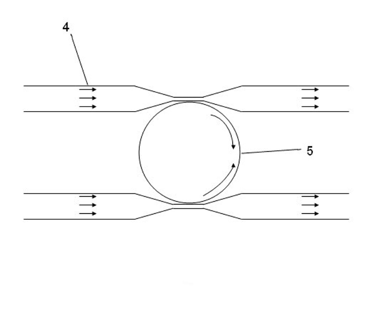
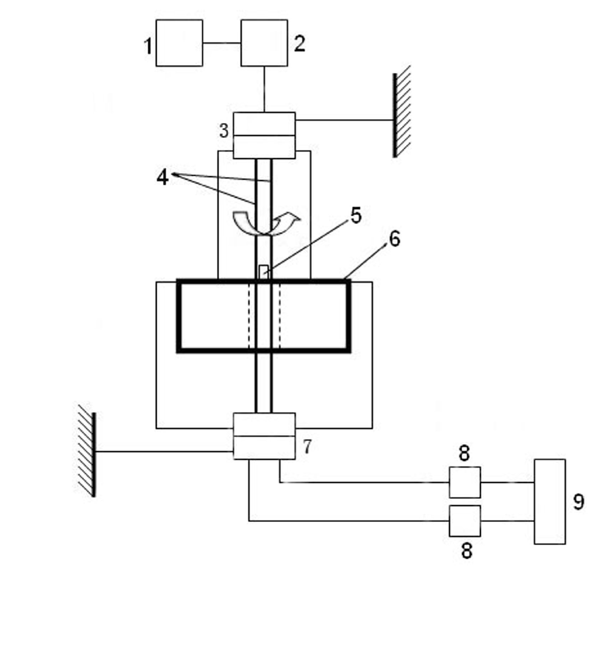
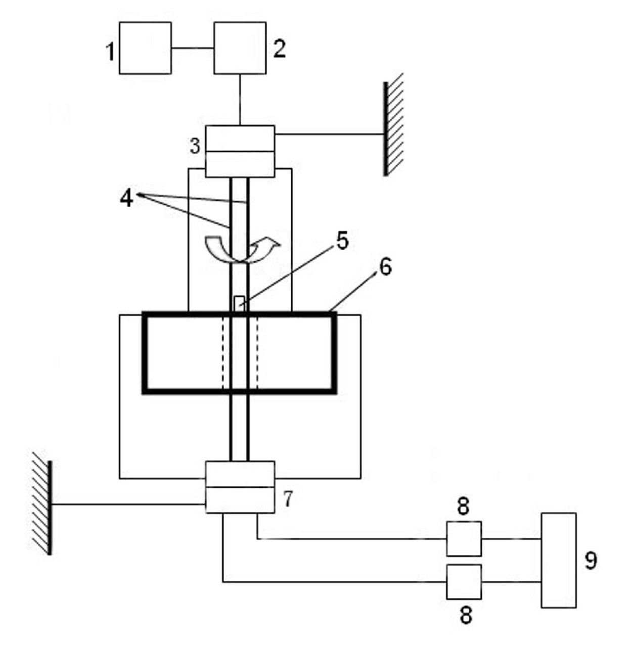
[0010] A simple structure for verification of the optical gyro effect, comprising a hollow turntable 6, a ring resonator 5 fixed at the center of the surface of the hollow turntable 6, and a double waveguide 4 coupled with the ring resonator 5; the double waveguide 4 runs through the surface of the hollow turntable 6 , the upper and lower sides of the hollow turntable 6 are respectively provided with a three-channel optical fiber rotary interconnection device 3 and a four-channel optical fiber rotary interconnection device 7; wherein, the lower part of the three-channel optical fiber rotary interconnection device 3 is connected to the four-channel optical fiber rotary interconnection device through a double waveguide 4 The lower part of the connecting device 7 is connected; the upper part of the three-channel optical fiber rotary interconnection device 3 is connected with an erbium-doped fiber amplifier 2 through an optical fiber, and the input end of the erbium-doped fiber ampl...


PUM


Abstract

The invention relates to a gyroscope inertia device, in particular to a simple structure for verifying optical gyroscopic effect. The invention solves the problems that the existing gyroscope inertia device is inconvenient to measure, is hard to further improve sensitivity and resolution, has high cost, is seriously affected by environment condition variation, such as temperature and the like and is difficult to integrate. The simple structure for verifying the optical gyroscopic effect comprises a hollow turntable, an annular resonant cavity and double waveguide, wherein the annular resonant cavity is fixed in the centre of a circle of the surface of the hollow turntable, the double waveguide is coupled with the annular resonant cavity and penetrates through the surface of the hollow turntable, and the upper side and the lower side of the hollow turntable are respectively provided with a three-channel optical fiber rotation interconnection device and a four-channel optical fiber rotation interconnection device. The invention effectively solves the problems that the existing gyroscope inertia device is inconvenient to measure, is hard to further improve sensitivity and resolution, has high cost, is seriously affected by environment condition variation, such as temperature and the like and is difficult to integrate, and the invention is suitable to serve as the core part of an inertial navigation system.

Description

technical field [0001] The invention relates to a gyro inertial device, in particular to a simple structure for verifying the optical gyro effect. Background technique [0002] As the core component of the inertial navigation system, gyro-inertial devices are widely used in the fields of homeland air defense, navigation guidance, control technology and other industries, as well as in industries such as robots and consumer electronics. Development is of great strategic importance. The existing gyro-inertial devices are mainly divided into traditional mechanical gyroscopes, micro-mechanical (MEMS) gyroscopes, optical gyroscopes (optical fiber gyroscopes, laser gyroscopes) and other types. Among them, traditional mechanical gyroscopes generally have problems such as large size, long start-up time, and movable parts, which make it difficult to achieve flexible measurement; micro-mechanical gyroscopes have developed rapidly in recent years, and their performance, accuracy, and r...

Claims


Application Information

Patent Timeline
Patent Type & Authority Applications(China)
IPC IPC(8): G01C25/00
Inventor 闫树斌薛晨阳刘俊张文栋张宇光李鹏严英占
Owner ZHONGBEI UNIV
Learn More