Control method of railway power regulator based on half-bridge structure

A technology of power conditioner and control method, applied in reactive power adjustment/elimination/compensation, reactive power compensation, AC network voltage adjustment and other directions, can solve problems such as voltage equalization, and achieve the effect of negative sequence and harmonic improvement

Inactive Publication Date: 2011-01-19
HUNAN UNIV
View PDF4 Cites 14 Cited by
  • Summary
  • Abstract
  • Description
  • Claims
  • Application Information

AI Technical Summary

Problems solved by technology

However, since the DC side voltage is powered by two seri

Method used


Image

  • Control method of railway power regulator based on half-bridge structure
  • Control method of railway power regulator based on half-bridge structure
  • Control method of railway power regulator based on half-bridge structure

Examples


Embodiment Construction

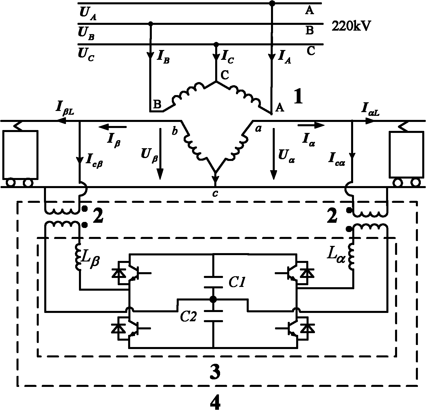
[0024] Such as figure 1 Shown is an application structure diagram of the control method of the present invention. The compensation object of the railway power conditioner 4 based on the half-bridge structure is a high-speed railway power supply system using a three-phase V / V traction transformer 1 . The railway power conditioner 4 based on the half-bridge structure is composed of two single-phase step-down transformers 2 and back-to-back half-bridge inverter modules 3 . The primary sides of the two single-phase step-down transformers are respectively connected to the two single-phase traction power supply arms, and the secondary sides of the two single-phase step-down transformers are connected to the power conversion module. The non-floating ground wires on the secondary side of the two single-phase step-down transformers are respectively connected to the midpoint of the switching arm of the power conversion module through the output reactor, and the floating ground of the s...


PUM


Abstract

The invention discloses a control method of a railway power regulator based on a half-bridge structure. The railway power regulator based on the half-bridge structure is composed of two half-bridge arms, and the two half-bridge arms are connected with each other by two capacitors. Since the voltage at the DC side is powered by two series capacitors, the problem of voltage sharing exists. In orderto realize voltage sharing at the DC side, a voltage sharing PI regulator is used for controlling the deviation of the two capacitor voltages, and the offset output by the voltage sharing regulator directly influences the charging and discharging current of the two capacitors, thereby reducing the deviation to 0. In order to keep the voltage at the DC side stable, the voltage external ring at theDC side uses a PI controller to regulate the output value, and the output value is respectively multiplied by the synchronizing signals of the two power supply arms, and superposed by the harmonic and negative sequence compensating current reference signal obtained by computation according to the VV traction system negative sequence and the harmonic compensation principle, thereby obtaining the current reference signal of the two half-bridge converters. In order to realize quick tracking of internal ring current, a hysteresis control method is used for the output currents of the two converters, so that the currents from the output ends of the two converters track the reference compensating signal, thereby realizing negative sequence and harmonic compensation.

Description


Claims


Application Information

Patent Timeline
IPC IPC(8): H02J3/12H02J3/18H02J3/01
CPCY02E40/30Y02E40/40
Inventor 罗安马伏军吴传平吴敬兵孙娟王刚张寅孙运宾
Owner HUNAN UNIV
Why Eureka
Try Eureka