
High-frequency high-voltage switching power supply for electric precipitation

A high-frequency high-voltage, switching power supply technology, applied in the direction of high-efficiency power electronic conversion, power supply technology, electrical components, etc., can solve the problems of high-frequency high-voltage switching power supply design difficulties, etc., and achieve the effect of light weight, high power factor, and small size

Inactive Publication Date: 2011-01-26
UNIV OF SHANGHAI FOR SCI & TECH
View PDF4 Cites 35 Cited by
  • Summary
  • Abstract
  • Description
  • Claims
  • Application Information

AI Technical Summary

Problems solved by technology

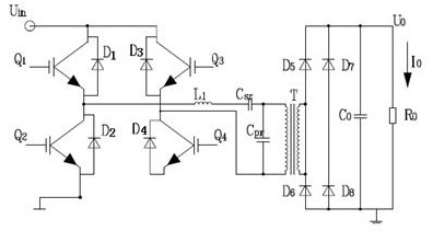
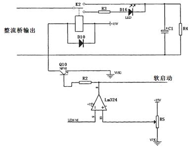
[0003] The present invention aims at the problem of difficult design of high-frequency and high-voltage switching power supply for electric dust removal, and proposes a high-frequency and high-voltage switching power supply for electric dust removal, which adopts a full-bridge inverter circuit with a series-parallel resonance soft switch and a high-frequency boost circuit , High-voltage silicon stack rectifier circuit, with functions such as short-circuit and over-current protection, soft start when starting up, tracking the resonant current to realize the tracking control of the resonant frequency, etc.

Method used


Image

  • High-frequency high-voltage switching power supply for electric precipitation
  • High-frequency high-voltage switching power supply for electric precipitation
  • High-frequency high-voltage switching power supply for electric precipitation

Examples


Embodiment Construction

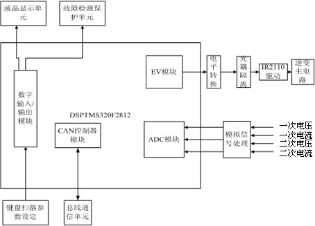
[0013] The system structure of the high-frequency high-voltage switching power supply based on DSP TMS320F2812 is as follows: figure 1 As shown, the main circuit is the input three-phase 380V50Hz AC power supply, which becomes 530V DC voltage through the three-phase rectification filter circuit 1, and then passes through the high-frequency inverter circuit 2 composed of IGBT modules, and the high-frequency pulse transformer 3 is boosted by high-voltage The silicon rectifier stack 4 becomes 72kV high-voltage direct current to the electrostatic precipitator 5; the DSP controller 7 realizes the H-bridge triggering of the high-frequency inverter circuit 2, and the input side of the electrostatic precipitator is connected to 6 pairs of voltage and current detection boards to complete the detection of voltage and current, and the signal Input the DSP controller 7 to adjust the high-frequency inverter circuit 2 through the DSP controller 7, and the DSP controller is connected with the...


PUM


Abstract

The invention relates to a high-frequency high-voltage switching power supply for electric precipitation. Three-phase alternating-current is input and converted into direct current by a three-phase rectifier filter circuit and then the direct current passes through a high-frequency inverter circuit; a series-parallel connection resonant soft switching circuit is connected between two inverter bridge arms in the high-frequency inverter circuit; the output of the series-parallel connection resonant soft switching circuit is boosted by a high-frequency pulse transformer, the boosted output passes through a high voltage silicon rectifier stack to form high-voltage direct current and the high-voltage direct current is input into an electric precipitator; a DSP controller outputs a control signal to the high-frequency inverter circuit; the input side of the electric precipitator is connected with a voltage and current detection circuit; the detection circuit detects voltage and current and inputs a signal into the DSP controller; the high-frequency inverter circuit is adjusted by the DSP controller; and the DSP controller is connected with an upper computer through a CAN interface so asto realize optimal control. The switching power supply is used for electric precipitation equipment and has the advantages of small volume, light weight, light harmonic pollution, high power factor, high conversion efficiency, and capability of generating waveforms meeting various working condition requirements of the electric precipitation equipment so as to realize energy conservation and emission reduction.

Description

technical field [0001] The invention relates to a switching power supply, in particular to a high-frequency and high-voltage switching power supply for electric dust removal. Background technique [0002] At present, due to the increasingly serious environmental pollution and energy shortage, in order to save energy and reduce emissions, it has become an inevitable trend to replace the traditional thyristor power frequency transformer mode with the high-frequency mode driven by IGBT in the high-voltage power supply of the electrostatic precipitator. With the rapid development of electronic devices, it is also possible to replace the traditional thyristor power supply with high-frequency and high-voltage switching power supply in actual production. The high-frequency high-voltage switching power supply can not only optimize the operation of the electrostatic precipitator, realize energy saving and emission reduction, but also has the following advantages: In terms of energy s...

Claims


Application Information

Patent Timeline
IPC IPC(8): B03C3/66H02M3/335H02M1/36
CPCY02B70/1491Y02B70/1433Y02B70/10
Inventor 高立颍张潮海金志辉栾天
Owner UNIV OF SHANGHAI FOR SCI & TECH
Learn More