Adjustable knife rest
An adjustable, tool holder technology, applied in metal processing equipment and other directions, can solve problems such as inability to meet production capacity requirements, and achieve the effects of simple and convenient production and processing, rich resources, and improved processing speed and efficiency.
Inactive Publication Date: 2011-01-26
扬州华宇管件有限公司
View PDF4 Cites 7 Cited by
- Summary
- Abstract
- Description
- Claims
- Application Information
AI Technical Summary
Problems solved by technology
[0005] Although people have designed various adjustable tool holders, the installation and replacement of existing machining tools for large-scale workpieces are still far from meeting the existing production capacity requirements.
Method used
View moreImage
Smart ImageViewing Examples

Examples
Embodiment Construction
Login to View More PUM
 Abstract
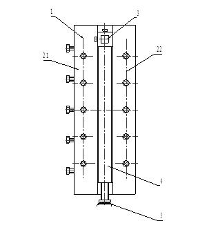
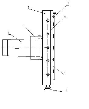
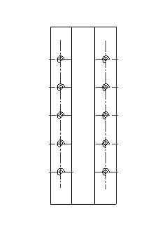
The invention discloses an adjustable knife rest. The adjustable knife rest comprises an 80-degree tapered sleeve 6, a machine tool fixing sleeve 7, a 6136 small-planker dial plate 5 and a knife rest fixing block 1, wherein a rectangular groove is formed on the knife rest fixing block 1; two pressing plates 21 and 22 cover on the two sides of the rectangular groove; a knife clamping block 3 and a sliding block 4 are positioned in the rectangular groove and can slide in the rectangular groove; the two ends of the sliding blocks are connected with the knife clamping block 3 and the 6136 small-planker dial plate 5 respectively; the knife rest fixing block 1 is fixedly connected with the 80-degree tapered sleeve 6 and the machine tool fixing sleeve 7; and the machine tool fixing sleeve 7 is connected with a main shaft of the machine tool. In the knife rest, when pipe fittings are machined, the machining cutters of pipe fitting machines with different pipe diameters can be positioned through the 6136 small-planker dial plate 5 and a fine adjustment mechanism without disassembling the knife rest, installing or debugging the cutters, so the adjustable knife rest has the advantages of time saving, high efficiency, accurate positioning, high machining precision and capacity of meeting the requirements of the pipe fitting machines with different pipe diameters on the machining precision.
Description
Technical field [0001] The invention relates to a tooling fixture for machining, in particular to an adjustable tool holder. Background technique [0002] The existing machining of larger size workpieces is mainly carried out on milling and boring machines. The machining of different sizes of workpieces requires disassembly of the tool holder and reinstallation of the tools. The removal, installation and debugging of the tool holder is time-consuming, labor-intensive and cumbersome. The adjustable tool post is mainly used for the installation of machining tools for workpieces of different specifications. [0003] A Chinese patent named "Adjustable Tool" (Application No. 98245167) discloses a tool for a lathe or a boring machine. It consists of a tool holder, a tool holder and a tool head. The tool holder has a cylindrical through hole in the transverse direction and the rear end of the tool holder. It is placed in the cylindrical through hole of the tool holder. The front end of t...
Claims
Login to View More Application Information
Patent Timeline
 Patent Type & Authority Applications(China)
IPC IPC(8): B23B21/00
Inventor 林恒龙蒯尧山何广熟
Owner 扬州华宇管件有限公司
Features
- R&D
- Intellectual Property
- Life Sciences
- Materials
- Tech Scout
- Unparalleled Data Quality
- Higher Quality Content
- 60% Fewer Hallucinations
Learn More Browse by: Latest US Patents, China's latest patents, Technical Efficacy Thesaurus, Application Domain, Technology Topic, Popular Technical Reports.
© 2025 PatSnap. All rights reserved.Legal|Privacy policy|Modern Slavery Act Transparency Statement|Sitemap|About US| Contact US: help@patsnap.com