Steady flow cooler

A cooler and steady flow technology, which is applied in the field of steady flow coolers, can solve the problems of not being able to dynamically push materials, not being able to achieve cooling air distribution, and not being able to achieve cooling effects, etc., to achieve high strength and rigidity, and improve cooling efficiency and cooling effect , Easy installation and maintenance

Active Publication Date: 2011-01-26
江苏鹤林智能机械有限公司
View PDF6 Cites 1 Cited by
  • Summary
  • Abstract
  • Description
  • Claims
  • Application Information

AI Technical Summary

Problems solved by technology

The best cooling air distribution cannot be achieved, and the best cooling effect cannot be achieved with the least cooling air
At the same time, the cooler drives the movable grate plate to push the material forward at the same tim

Method used


Image

  • Steady flow cooler
  • Steady flow cooler
  • Steady flow cooler

Examples


Embodiment Construction

[0034] Below in conjunction with accompanying drawing, the utility model is described in detail:

[0035] 1. New hot end fixed grate bed:

[0036] 1. Innovatively designed box structure

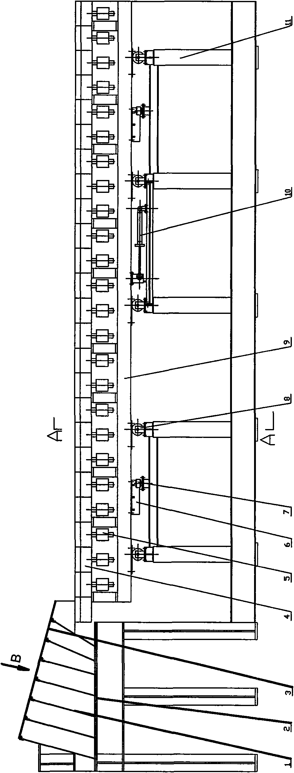
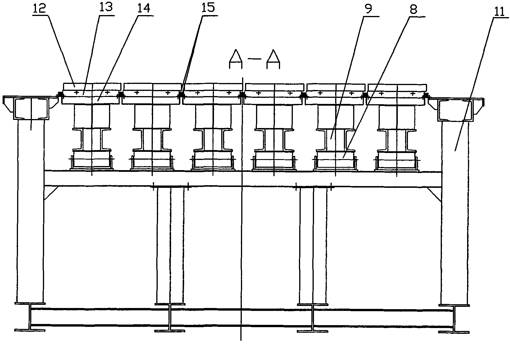
[0037] Welded by steel plate as attached image 3 The hot end of the fixed grate bed air supply device 1 has a box-type structure, and the box is divided into several small squares by criss-cross partitions. A front grate plate 3 is installed on the upper part of each small square. The fixed grate bed 2 is inclined Installed downwards on the support, each front grate plate 1 forms an obliquely downward plane.

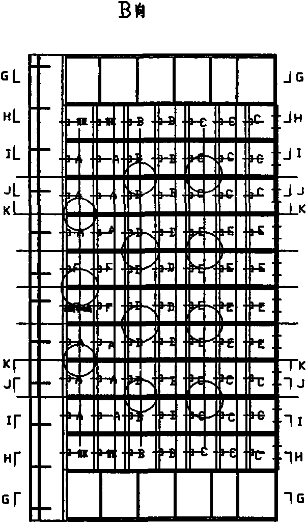
[0038] 2. Separate air supply for the fixed grate bed 2, and each partition divides the box into A, B, C, D, E, F areas and blind areas, and the air is supplied by different air ducts 16, which can be cooled according to the cooling of each area. Conditions, clinker layer thickness, etc. determine the air pressure and air volume of the air supply, realize more detailed control flow ...


PUM


Abstract

The invention discloses a steady flow cooler, which relates to the steady flow cooler for cooling and conveying high-temperature cement clinker and the like. The steady flow cooler comprises a bracket, a fixed grate bed and a movable grate bed which are engaged on the bracket, wherein the fixed grate bed and the movable grate bed are provided with an air supply device respectively; a drive device and a guide device are arranged below the movable grate bed; the fixed grate bed has a box-type structure and is partitioned into a plurality of units by partition boards, a front grate plate arranged obliquely downwards is arranged above each unit, a plurality of adjacent front grate plates form an area, an independent air supply device is arranged below each area, and the air pressure and the air quantity of the each air supply device are controlled by a control unit; and the movable grate bed comprises a plurality of movable longitudinal beams arranged on the bracket and driven to run by the drive device and the guide device, a plurality of independent rear grate plates are arranged on each movable longitudinal beam, and an air supply device with adjustable air pressure and air quantity is arranged below the rear grate plates respectively. The steady flow cooler greatly improves the cooling efficiency and the cooling quality of the cement clinker.

Description

technical field [0001] The invention relates to a steady-flow cooler for cooling and transporting high-temperature cement clinker. Background technique [0002] As an important main equipment of the clinker burning system in a cement plant, the cooler is responsible for multiple functions such as cooling, heat recovery, transportation, and crushing of high-temperature red-hot clinker. With the gradual improvement of modern new dry-process cement production technology, the production scale is developing towards large-scale development. One of the key factors is the large-scale equipment and the application of high-tech, and the cooling machine with high efficiency, energy saving and reliable operation has become a guarantee. The whole system has strong production capacity, low energy consumption, high operation rate and a very important factor for the stable operation of the system. [0003] The fixed grate bed at the hot end of the domestic traditional cooler is to install ...

Claims


Application Information

Patent Timeline
IPC IPC(8): F27D15/02C04B7/47
CPCY02P40/121
Inventor 杨生强吴瑞煜
Owner 江苏鹤林智能机械有限公司
Why Eureka
Try Eureka