Sound source positioning device

A sound source localization and sound source technology, applied in the direction of localization, measurement devices, instruments, etc., can solve the problems of redundant and complex structure, affecting the accuracy of measurement, and error of sound source target localization accuracy.

Inactive Publication Date: 2011-01-26
HEBEI UNIV OF TECH
View PDF5 Cites 38 Cited by
  • Summary
  • Abstract
  • Description
  • Claims
  • Application Information

AI Technical Summary

Problems solved by technology

[0003] Most of the existing sound source localization devices can only locate the sound source target in an ideal environment without background noise, and their structures are redundant and complex
Because the sound wave is very sensitive, the measured sound field is easily disturbed by the measuring device itself, thus affecting the accuracy of the measurement
If the number of sensors in the microphone array is large and the structure is relatively complex, it not only requires higher production costs, but also directly affects the free diffusion of sound waves, which will lead

Method used


Image

  • Sound source positioning device
  • Sound source positioning device
  • Sound source positioning device

Examples


Embodiment 1

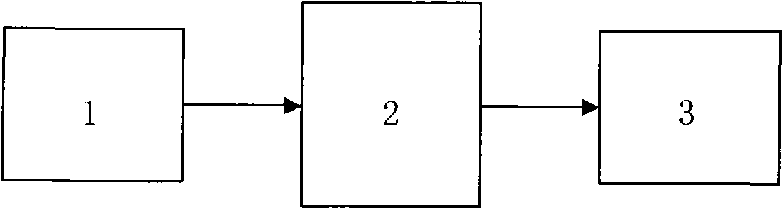
[0075] The positioning calculation method in the upper computer system 3 of a sound source localization device is as follows:

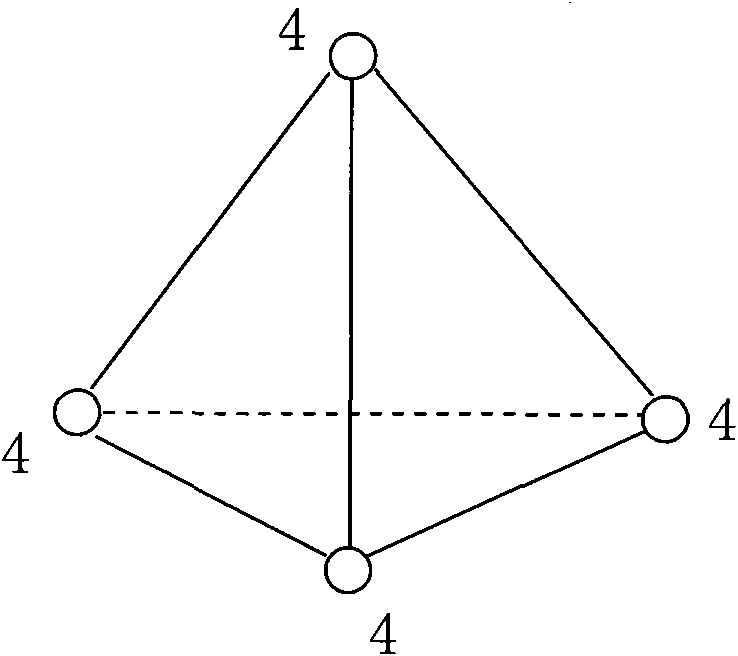
[0076] In the structure of the regular tetrahedral array shown in Figure 10,

[0077] The four vertices S of the regular tetrahedron 1 , S 2 , S 3 and S 4They are four microphones respectively, O is the origin of the Cartesian coordinate system, and is also the center of the bottom surface of the regular tetrahedron. Let Q be the target point, the coordinates are Q(x, y, z), and the distance from the origin of the coordinates to the target point OQ Be r meters, the projection of OQ on the XOY plane is OQ', define the angle between OQ' and the X-axis as α, and the angle between OQ and the Z-axis is β;

[0078] Suppose S 1 The distance to the coordinate origin O is a=0.141 meters, then the coordinates of the four microphones are:

[0079] S 1 =(a,0,0), and

[0080] If c is the speed of sound, let the distances from Q to the four microph...

Embodiment 2

[0088] Except that the distance r from the designed sound source to the microphone array is 2.07 meters, and the spacing d of each microphone is 23 centimeters, that is Others are the same as embodiment 1, and finally draw the azimuth angle formula of the sound source as:

[0089] α ≈ arctan ( 3 d 42 - d 43 d 42 + d 43 - 2 d 41 ) .

Embodiment 3

[0091] Except that the distance r from the designed sound source to the microphone array is 3 meters, and the spacing d of each microphone is 24 cm, that is Others are the same as embodiment 1, and finally draw the azimuth angle formula of the sound source as:

[0092] α ≈ arctan ( 3 d 42 - d 43 d 42 + d 43 - 2 d 41 ) .


PUM


Abstract

The invention relates to a sound source positioning device, applying sound waves to position through the match of a plurality of directions, which is a three-dimensional space sound resource object positioning device. The sound resource positioning device is composed of a hearing transducer, a sound resource signal microprocessor and an upper computer system, wherein the hearing transducer is a microphone array of a four-dimension regular tetrahedron structure; four microphones are respectively positioned on the four top points of the regular tetrahedron structure; the sound resource signal microprocessor is composed of a sound signal amplifier module, an analysis latch module and a communication transmission module; the upper computer system is composed of a positioning calculation method and peripheral equipment; and the hardware parts of each part and each module are all connected with each other through wires. The sound resource positioning device realizes accurate positioning to sound resources at any position in a three-dimensional space, is constructed into an all-around hearing scene, has the advantages of simple structure and higher precision, and has an anti-noise ability.

Description

technical field [0001] The technical solution of the present invention relates to a device for positioning by determining the cooperation of multiple directions by applying sound waves, specifically a sound source localization device. Background technique [0002] Nowadays, with the continuous expansion of the application field of bionic technology, auditory perception technology based on microphone array has gradually become an important topic in many research fields such as mobile robot navigation, speech signal enhancement and underwater target perception. It can be said that hearing is one of the important symbols of the new generation of intelligent robots and an important means to realize the "human-machine-environment" interaction. Because sound has the characteristic of bypassing obstacles, in a multi-information collection system, hearing can cooperate with vision to make up for the limitation of its limited field of view and the inability to pass through non-transp...

Claims


Application Information

Patent Timeline
IPC IPC(8): G01S5/18G01S5/30
Inventor 杨鹏孙昊祖丽楠谷岳徐勤奇孙海荣何蒙
Owner HEBEI UNIV OF TECH
Why Eureka
Try Eureka