Permanent magnet rotating motor with high torque density, high power density and low disturbance

A high power density, rotating electrical machine technology, applied in the direction of synchronous machine parts, magnetic circuit shape/style/structure, winding conductor shape/style/structure, etc., can solve the problem of poor heat dissipation of the rotor and shaft, and achieve reduction Effect of torque disturbance, increasing torque density and power density

Active Publication Date: 2011-01-26
SHANGHAI CHUANLIN PRECISION PARTS CO LTD
View PDF5 Cites 4 Cited by
  • Summary
  • Abstract
  • Description
  • Claims
  • Application Information

AI Technical Summary

Problems solved by technology

For conventional radial motors, this improvement has its inherent limitations. This is because: the bottleneck characteristics of the path at the root of the rotor tooth shape; a considerable part of the rotor core on the circumference of the rotor yoke is difficult to use as a magnetic circuit; Thermal migration of the stator windings to the stator core and then to the support structure - poor heat dissipation from the rotor and shaft through the stator air gap without forced cooling arrangements

Method used


Image

  • Permanent magnet rotating motor with high torque density, high power density and low disturbance
  • Permanent magnet rotating motor with high torque density, high power density and low disturbance
  • Permanent magnet rotating motor with high torque density, high power density and low disturbance

Examples


Embodiment Construction

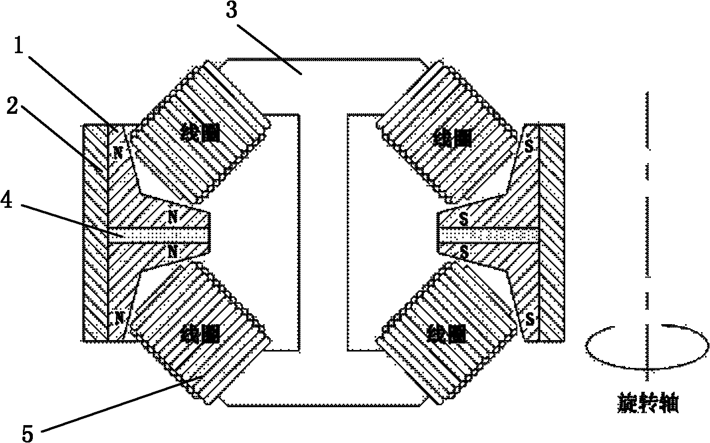
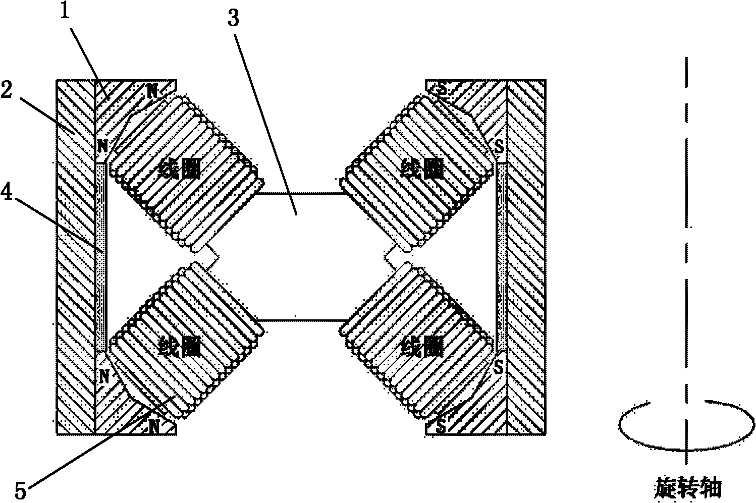
[0030] Please refer to the attached figure 1 , 2 , 3, 4, 5, and 6 show that the arrangement of permanent magnets in space is sequentially expanded along the perimeter and arranged in a double V shape, that is, two pairs of V-shaped permanent magnets of the same polarity are used along the perimeter. arrangement;

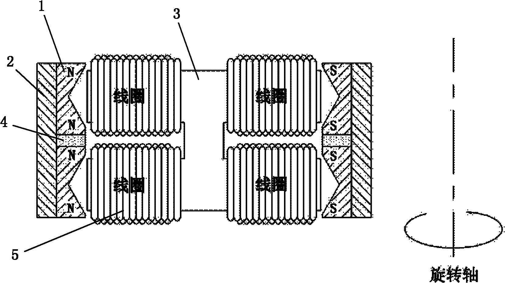
[0031] In the radial direction, corresponding to it, on the inner surface of the double V-shaped magnetic steel, there are two pairs of V-shaped magnetic steels of the same polarity arranged along the circumference. When the rotor is outside, the opposite type (such as attached figure 1 ), in the case of including the rotor, adopt the back-to-back type (as attached Figure 5 ).

[0032] In the axial direction, that is, two pairs of V-shaped permanent magnets with the same polarity are arranged on the upper and lower sides of the rotating shaft. The polarity of the magnet is reversed. In this axial magnetic steel arrangement, the winding direction of the upper a...


PUM


Abstract

The invention aims at providing a novel topological structure of a motor, which generally has the structural characteristics of a radial motor and an axial motor, not only utilizes the electromagnetic space inside the motor to maximum extent, eliminates the bottleneck of the radial motor and realizes the high torque density and the high power density of the rotating motor, but also can provide more space for controlling the motor, so that the disturbance on the torque of the motor is reduced to minimum extent. The technical scheme of the invention is that permanent magnetic steel of the motor is sequentially extended along the circumferential line and is arrayed in a V shape, that is to say, two pairs of V-shaped homopolar permanent steel are arrayed along the circumferential line and adjacent pairs of magnetic steel have opposite polarities; two pairs of homolar permanent magnetic steel groups are arranged in the axial direction, that is to say, at the upper part and the lower part of a rotating shaft; and two pairs of magnetic steel have opposite polarity to the above pairs of homopolar V-shaped permanent steel. A corresponding coil winding pair group is respectively arranged opposite to two pairs of V-shaped magnetic steel.

Description

technical field [0001] The invention relates to the technical field of motors. Background technique [0002] The commonly used radial motor means that the direction of the magnetic field in the air gap is radial. The magnetic field mentioned here, for a permanent magnet motor, refers to the magnetic field excited by the permanent magnet and the magnetic field excited by the coil winding when the motor is working. For a conventional radial machine, the directions of these two magnetic vectors are generally radial in the gap. The axial motor corresponding to the radial motor is also called a disc motor, and the direction of the magnetic field in the air gap is roughly parallel to the rotation axis of the motor [1]. The magnetic field mentioned here, for the permanent magnet brushless motor, also refers to the magnetic field excited by the permanent magnet and the magnetic field excited by the stator coil winding when it is working. For conventional axial motors, or disk mot...

Claims


Application Information

Patent Timeline
Patent Type & Authority Applications(China)
IPC IPC(8): H02K21/02H02K1/06H02K3/04
Inventor 陆炳林
Owner SHANGHAI CHUANLIN PRECISION PARTS CO LTD
Why Eureka
Try Eureka