
Member for miniaturizing molten glass droplet, method for producing glass gob, method for producing glass molding, and method for producing minute glass droplet

A technology of molten glass and a manufacturing method, which is applied in the fields of molten glass drop miniaturization components, glass clot manufacturing, glass forming body manufacturing, and glass micro droplet manufacturing, which can solve problems such as a lot of labor and time, and achieve position deviation reduction, The effect of sufficient stability of product quality

Inactive Publication Date: 2013-09-04
KONICA MINOLTA OPTO
View PDF3 Cites 0 Cited by
  • Summary
  • Abstract
  • Description
  • Claims
  • Application Information

AI Technical Summary

Problems solved by technology

[0004] As the glass preforms used in the reheat molding method, ground preforms produced by grinding and grinding etc. mechanical processing have been used in the past. However, there is a problem that a lot of labor and time are required to manufacture the ground preforms.

Method used


Image

  • Member for miniaturizing molten glass droplet, method for producing glass gob, method for producing glass molding, and method for producing minute glass droplet
  • Member for miniaturizing molten glass droplet, method for producing glass gob, method for producing glass molding, and method for producing minute glass droplet
  • Member for miniaturizing molten glass droplet, method for producing glass gob, method for producing glass molding, and method for producing minute glass droplet

Examples


Embodiment 1~9

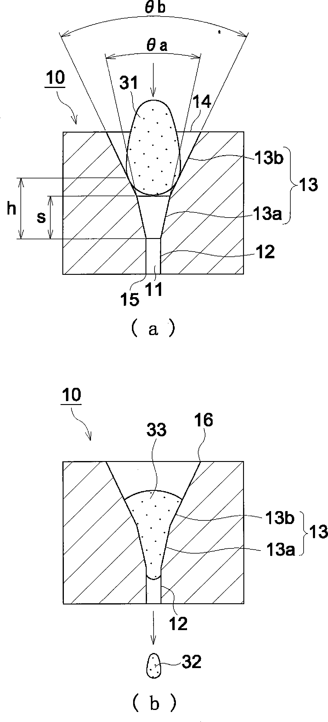
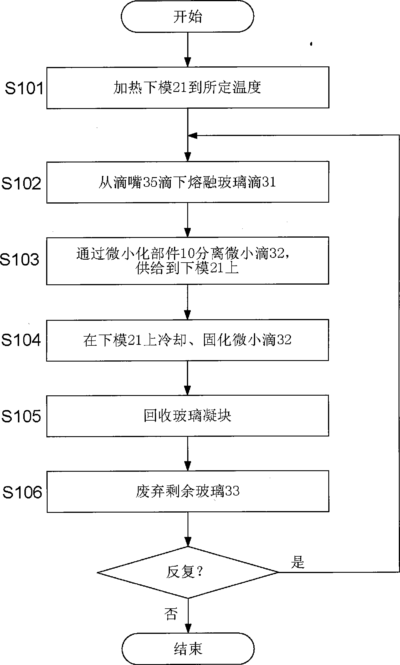
[0116] use as figure 1 The illustrated miniaturized component 10 having a conical portion 13 composed of two regions 13a, 13b with different conical opening angles is shown in accordance with image 3 In the flow shown, microdrops 32 are dropped on the lower mold 21 to make a glass gob.

[0117] Phosphoric acid-based glass with a Tg of 530° C. was used as the glass material, and molten glass drops 31 were dropped from a platinum drip nozzle 35 with an outer diameter of φ6 mm. The mass of the molten glass drop 31 dripped from the drip nozzle 35 was 250 mg.

[0118] The miniaturized component 10 employs nine types of cone portions 13 with different cone opening angles and heights (Examples 1 to 9). In Table 1, the cone opening angle θb of the area 13b that first contacts the molten glass drop 31, the cone opening angle θa of the area 13a closest to the straight portion 12, the height h of the entire area of ​​the conical portion 13 that contacts the molten glass 31, The heigh...

Embodiment 10、11

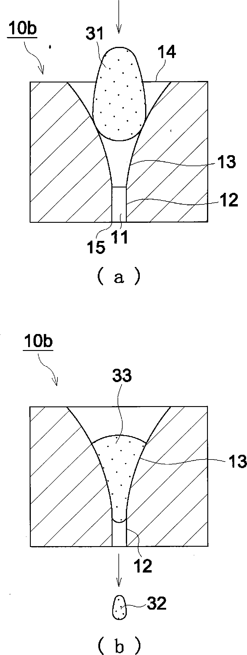
[0123] Adopted as a miniaturized part figure 2 The miniaturized component 10b is shown. The cross-sectional shape of the conical portion 13 including the central axis of the through hole 11 is substantially arc-shaped. There are two types of cone opening angles at the position of contacting the molten glass drop 31 first: 45° (Example 10) and 60° (Example 11). The opening angle of the cone decreases continuously as the straight portion approaches, and the boundary portion with the straight portion 12 is almost 0°. The straight portion 12 has a diameter of φ2 mm and a length of 5 mm.

[0124] Using the two types of miniaturized components 10b described above, 100 glass molded bodies were produced in the same manner as in Examples 1 to 9, and mass deviation and positional deviation were determined. The results are also presented in Table 1.


PUM

PropertyMeasurementUnit
lengthaaaaaaaaaa

Abstract

Inner circumferential surface of a through hole in a member for miniaturizing a molten glass droplet includes a tapered part having a diameter spreading toward an inlet through which a molten glass droplet enters and receiving a molten glass droplet, and a straight part having a substantially constant diameter and passing therethrough a molten glass droplet collided against the tapered part. An area of the tapered part which is in contact with a molten glass droplet (a) consists of a plurality of areas each having a different opening angle of a taper, wherein an area closer to the straight part has a smaller opening angle of a taper. (b) Alternatively, the opening angle of a taper becomes smaller continuously toward the straight part.

Description

technical field [0001] The present invention relates to a molten glass drop miniaturization member for colliding molten glass droplets in order to obtain molten glass droplet miniaturization, a method for producing a glass gob using the molten glass drop miniaturization member, a method for producing a glass molded article, and glass microdroplets manufacturing method. Background technique [0002] In recent years, glass optical elements have been widely used as lenses for digital cameras, optical pickup lenses such as DVDs, camera lenses for mobile phones, coupling lenses for optical communication, and the like. As such a glass optical element, a glass molded body produced by press-molding a glass material with a molding die is often used. [0003] As a method of manufacturing a glass molded body by press molding, two methods of a reheat press molding method and a droplet molding method are known. The reheat molding method is to heat and press the pre-made glass preform (...

Claims


Application Information

Patent Timeline
Patent Type & Authority Patents(China)
IPC IPC(8): C03B19/10C03B7/01C03B11/00
CPCC03B7/12C03B11/08
Inventor 釜田善浩小椋和幸
Owner KONICA MINOLTA OPTO
Learn More