
Pump

A technology of impeller and casing, which is applied in the field of pumps for transporting supercritical CO2 fluid or liquid CO2, which can solve the problems of reduced service life and achieve the effects of reducing loss, preventing interference and prolonging pump life

Inactive Publication Date: 2011-01-26
MITSUBISHI HEAVY IND LTD
View PDF1 Cites 2 Cited by
  • Summary
  • Abstract
  • Description
  • Claims
  • Application Information

AI Technical Summary

Problems solved by technology

However, when the wear of the ball bearings causes the main shaft and the impeller to move in the direction of the rotation axis, interference occurs between the impeller and the casing, resulting in a problem of reduced service life

Method used


Image

  • Pump
  • Pump
  • Pump

Examples


Embodiment

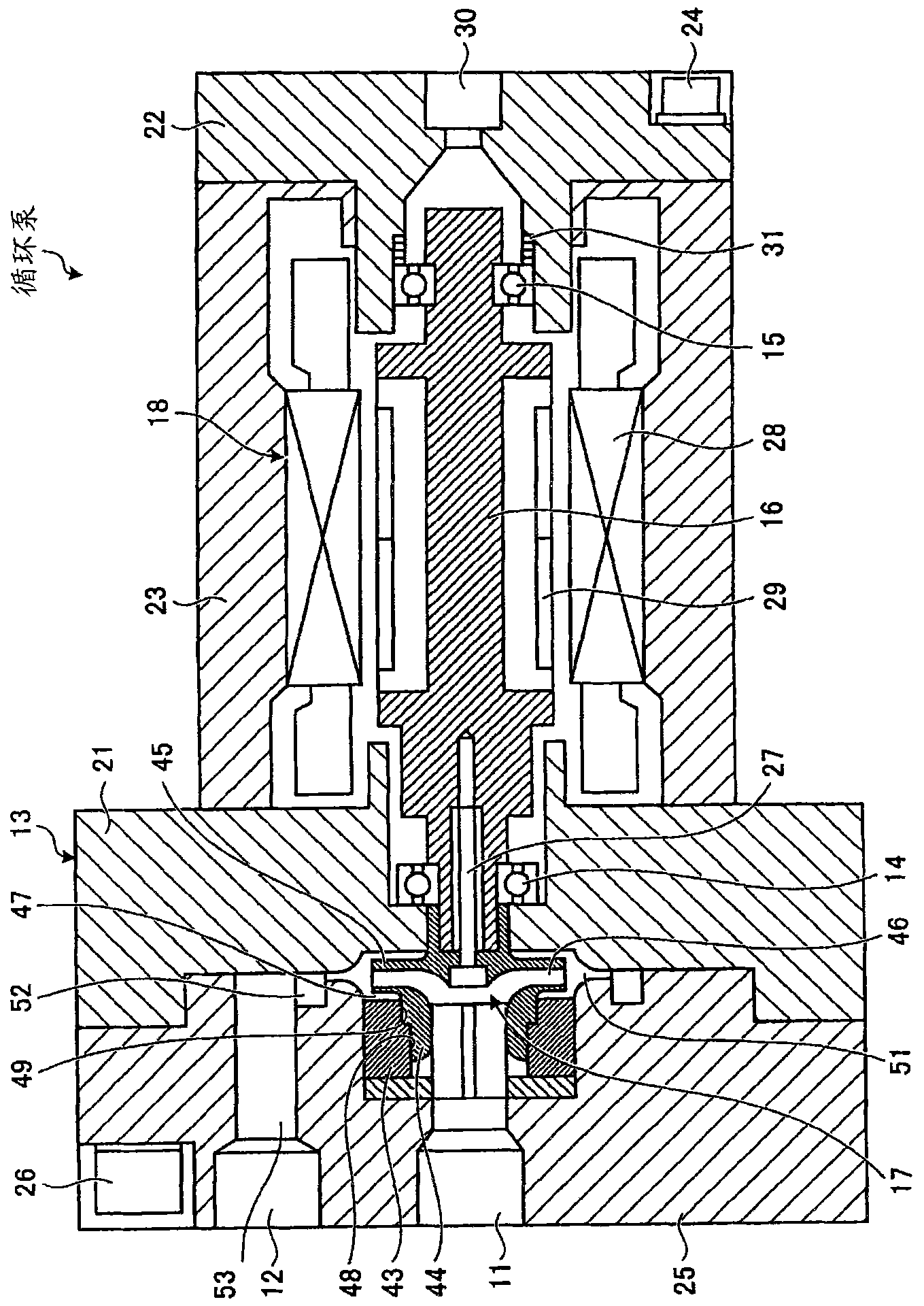
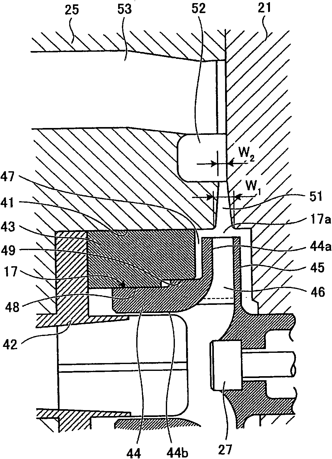
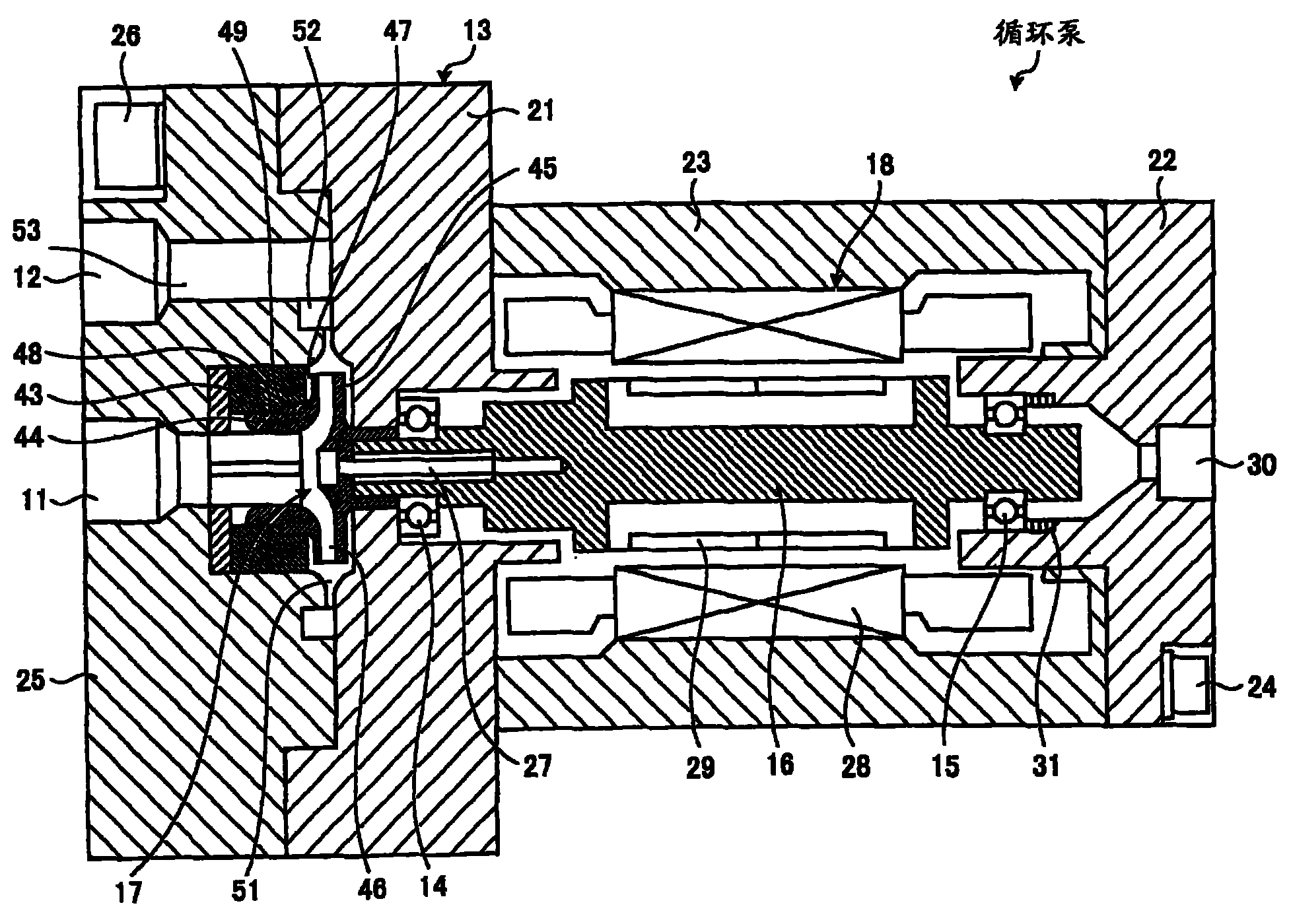
[0038] figure 1 In order to show that the pump related to an embodiment of the present invention is a cross-sectional view of a circulation pump for a semiconductor cleaning device, figure 2 It is an enlarged view showing the main part of the circulation pump for the semiconductor cleaning apparatus of this embodiment.

[0039] As shown in Fig. 1 and Fig. 2, the circulation pump for semiconductor cleaning device of this embodiment is provided with: a casing 13 having a suction port 11 and a discharge port 12; in this casing 13, ball bearings 14, 15 are used to rotate The main shaft 16 is freely supported; the impeller 17 connected to the shaft end of the main shaft 16; and the shield motor 18 capable of driving the rotating impeller 17 through the main shaft 16 are configured so that the fluid sucked by the suction port 11 can be boosted by the rotation of the impeller 17. Discharge from outlet 12.

[0040] The structure of the casing 13 is that the annular discharge and su...


PUM


Abstract

A pump having extended life. A main shaft (16) is rotatably supported in a casing (13) by ball bearings (14, 15), and the casing (13) has a suction opening (11) and a discharge opening (12). An impeller (17) is connected to an end of the main shaft (16), and the impeller (17) can be rotated by a canned motor (18) via the main shaft (16). A front shroud (44) is provided to the axial front portion of the impeller (17), and a rear shroud (45) is provided to the axial rear portion of the impeller (17). A predetermined axial gap (47) is formed between the casing (13) and the front shroud (44). Radial seal sections (48, 49) are arranged between the casing (13) and the front shroud (44).

Description

technical field [0001] The present invention relates, for example, to the handling of supercritical CO 2 Fluid or liquid CO 2 pump. Background technique [0002] Example: as the handling of supercritical CO 2 Fluid or liquid CO 2 The pump, there is a circulation pump for semiconductor cleaning. With the high integration of semiconductor devices in recent years, the processing line width of wafers is also required to be miniaturized. The current mainstream of 0.18 μm is expected to be 0.10 μm or less in the future. However, in the existing method of cleaning semiconductors with liquids such as ultrapure water, when the wafer is dried, the capillary force caused by the interfacial tension between the gas and the liquid sometimes causes the resist formed on the wafer to collapse (resist etchant collapse). [0003] In order to solve the above problems, semiconductor cleaning devices using supercritical fluids have been developed instead of conventional liquids such as ultr...

Claims


Application Information

Patent Timeline
Patent Type & Authority Applications(China)
IPC IPC(8): F04D29/08F04D13/06F04D29/046F04D29/44
CPCF04D29/167F04D29/047F04D7/02F04D29/049
Inventor 光田公彦山本康晴
Owner MITSUBISHI HEAVY IND LTD
Learn More