
Special lifting machine for lifting wind power generation equipment

A technology of wind power generation equipment and cranes, which is applied in the direction of cranes, etc., can solve the problems of large number of points in wind farms, lack of large machinery, and harsh hoisting environment, etc., to achieve convenient disassembly and transfer, many hoisting points, and high safety Effect

Active Publication Date: 2011-02-02
中昇建机(南京)重工有限公司
View PDF0 Cites 21 Cited by
  • Summary
  • Abstract
  • Description
  • Claims
  • Application Information

AI Technical Summary

Problems solved by technology

[0002] The development of wind power is too fast, there is a serious shortage of large-scale machinery, the number of wind farms is large, the distance between machine positions is too long, the lifting height is high, the weight is heavy, and the hoisting environment is harsh. In areas such as coastal beaches and islands, a crane is needed that can simultaneously realize fast transition, quick disassembly and assembly, good stability in wind-resistant hoisting, high lifting height and heavy weight, and can overcome harsh environments. The currently used 500t The above-mentioned large-scale truck cranes and large-scale crawler cranes above 450t cannot integrate many functions above, and are expensive, which does not meet the current national conditions. Therefore, truck cranes and crawler cranes are not ideal lifting equipment for wind power hoisting. In view of the current situation, It is necessary to develop a special crane suitable for hoisting wind power equipment to fill the domestic gap

Method used


Image

  • Special lifting machine for lifting wind power generation equipment
  • Special lifting machine for lifting wind power generation equipment
  • Special lifting machine for lifting wind power generation equipment

Examples


Embodiment Construction

[0050] Below in conjunction with accompanying drawing, the present invention will be further described:

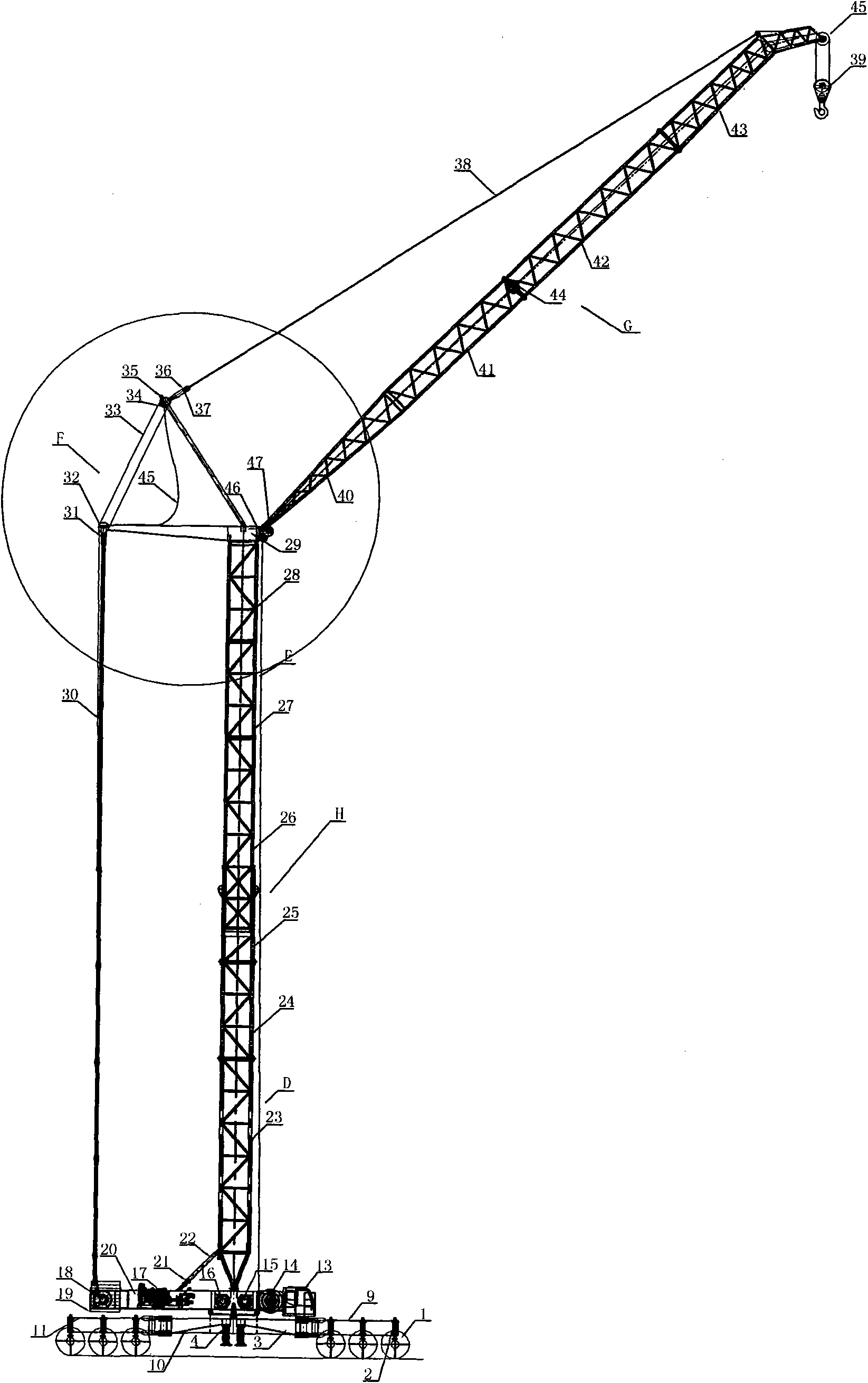
[0051] The special crane for wind power hoisting of the present invention includes a special walking chassis, a telescopic tower body H, a swing arm luffing mechanism F, a folding arm mechanism, and an electrical control unit. The electrical control unit can be automatically controlled by a PLC programmable controller. . Overall structure of the present invention is as figure 1 shown.

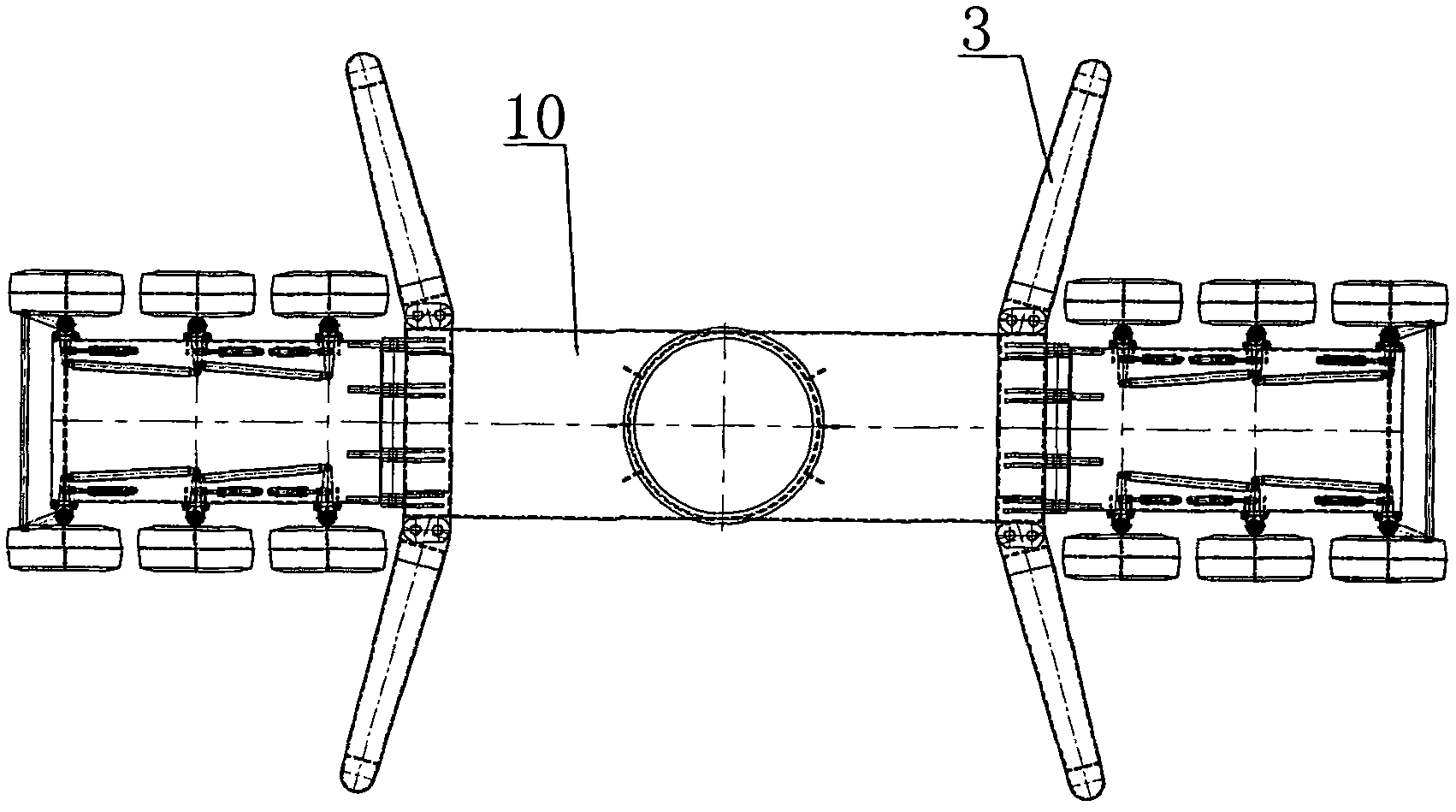
[0052] Such as figure 2 , image 3 As shown, the walking chassis of the present invention includes three parts, upper frame 20, lower frame A and slewing mechanism I, and lower frame A is divided into front, rear, and middle parts, which can solve the limitation of long-distance crane transportation on volume and Modular assembly; the front and rear parts are suspended with 6 walking tires, and the 6 tires are distributed on both sides. The whole vehicle has 12 tires. The driving tire ...


PUM


Abstract

The invention discloses a special lifting machine for lifting wind power generation equipment, which has the characteristics of low production cost, smooth operation of the whole machine, low requirements for roads and high field transferring speed. The lifting machine mainly comprises a running chassis, a tower body, a lifting arm, an amplitude variation mechanism of a swinging arm and an electrical control unit, wherein the running chassis comprises a lower frame (A), a slewing mechanism (I) and an upper frame (20), wherein the upper frame (20) is connected with the lower frame (A) through the slewing mechanism (I); and an operating room (13), a balancing weight (19), a power engine (17) and a winch are arranged on the upper frame (20). The invention aims to solve the problems of the lifting equipment required for installation of the wind power equipment; and the installation of the wind power equipment requires that the lifting capacity of the lifting equipment meets the requirement, the lifting height of the lifting equipment meets the requirement, and the lifting equipment needs to be capable of quickly transferring fields. The lifting machine can also be used for lifting in other building industries.

Description

(1) Technical field [0001] The present invention relates to a special hoisting machine for wind power hoisting, in particular to a tire-type walking mechanism, a special chassis, a vertically telescopic tower body, a swing-type luffing mechanism, and a foldable boom, especially a tire crane, a tower crane, and a car crane. Combined with the advantages of crawler cranes, it can be the first special crane in China. (2) Background technology [0002] The development of wind power is too fast, there is a serious shortage of large-scale machinery, the number of wind farms is large, the distance between machine positions is too long, the lifting height is high, the weight is heavy, and the hoisting environment is harsh. In areas such as coastal beaches and islands, a crane is needed that can simultaneously realize fast transition, quick disassembly and assembly, good stability in wind-resistant hoisting, high lifting height and heavy weight, and can overcome harsh environments. Th...

Claims


Application Information

Patent Timeline
IPC IPC(8): B66C23/16B66C23/62B66C23/68B66C23/82
CPCB66C23/185B66C23/82
Inventor 许贵林朱弘黄建军孙兴文孙正刚张施明吴玉水
Owner 中昇建机(南京)重工有限公司
Learn More