Method for improving weighing precision of charging system and device thereof

A feeding system and precision technology, which is applied in the field of feeding system to achieve the effects of improving production efficiency, increasing production cost and improving weighing accuracy

Inactive Publication Date: 2011-02-02
BAOSHAN IRON & STEEL CO LTD
View PDF4 Cites 17 Cited by
  • Summary
  • Abstract
  • Description
  • Claims
  • Application Information

AI Technical Summary

Problems solved by technology

The error caused by zero drift can be reduced by variou

Method used


Image

  • Method for improving weighing precision of charging system and device thereof
  • Method for improving weighing precision of charging system and device thereof
  • Method for improving weighing precision of charging system and device thereof

Examples


Embodiment 1

[0043] Such as Figure 5 The flow chart of the method for improving material weighing accuracy shown in this implementation includes:

[0044] S11, installing a preset compensation module with a standard weight greater than the maximum positive zero drift value and the maximum negative zero drift value of the weighing hopper on the weighing hopper to generate an original weighing value. There is no fixed requirement on the shape of the preset compensation module, which is convenient to pick and place, such as standard weights. When calibrating the weighing hopper, the preset compensation module is usually removed, and the preset compensation module is put on after calibration.

[0045]Due to the existence of the preset compensation module, there is always a positive original weighing value in the weighing hopper before the material is weighed. Generally, the maximum positive zero drift value and the maximum negative zero drift value are not too large, for example, 20 kg, the...

Embodiment 2

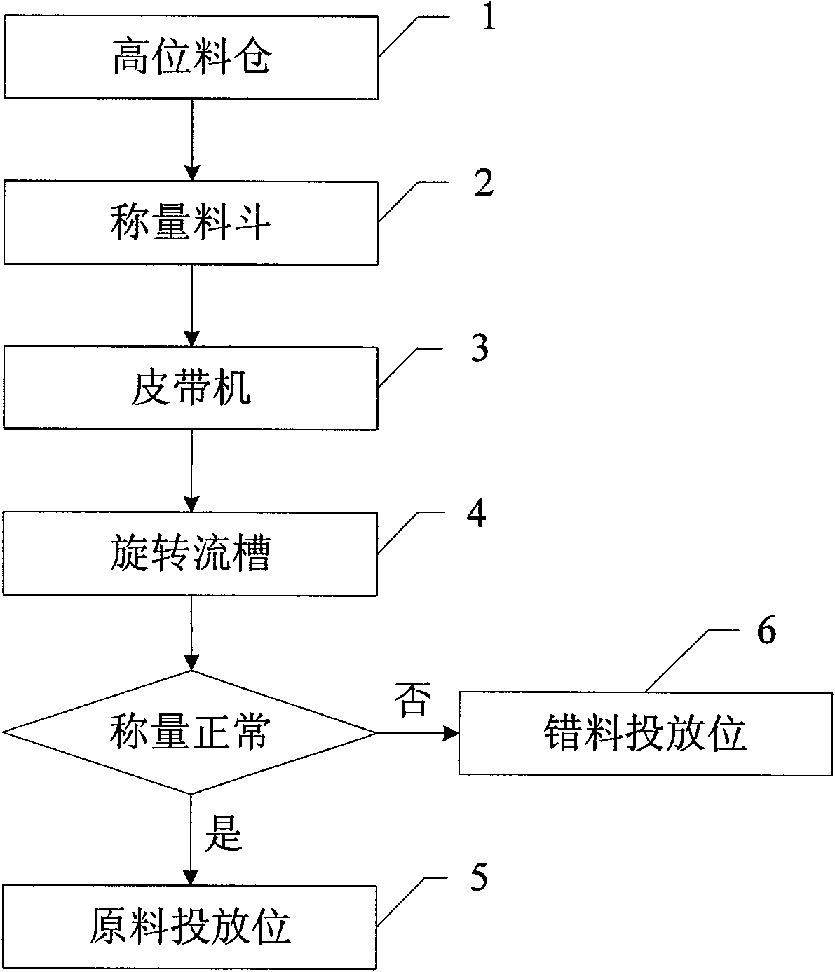
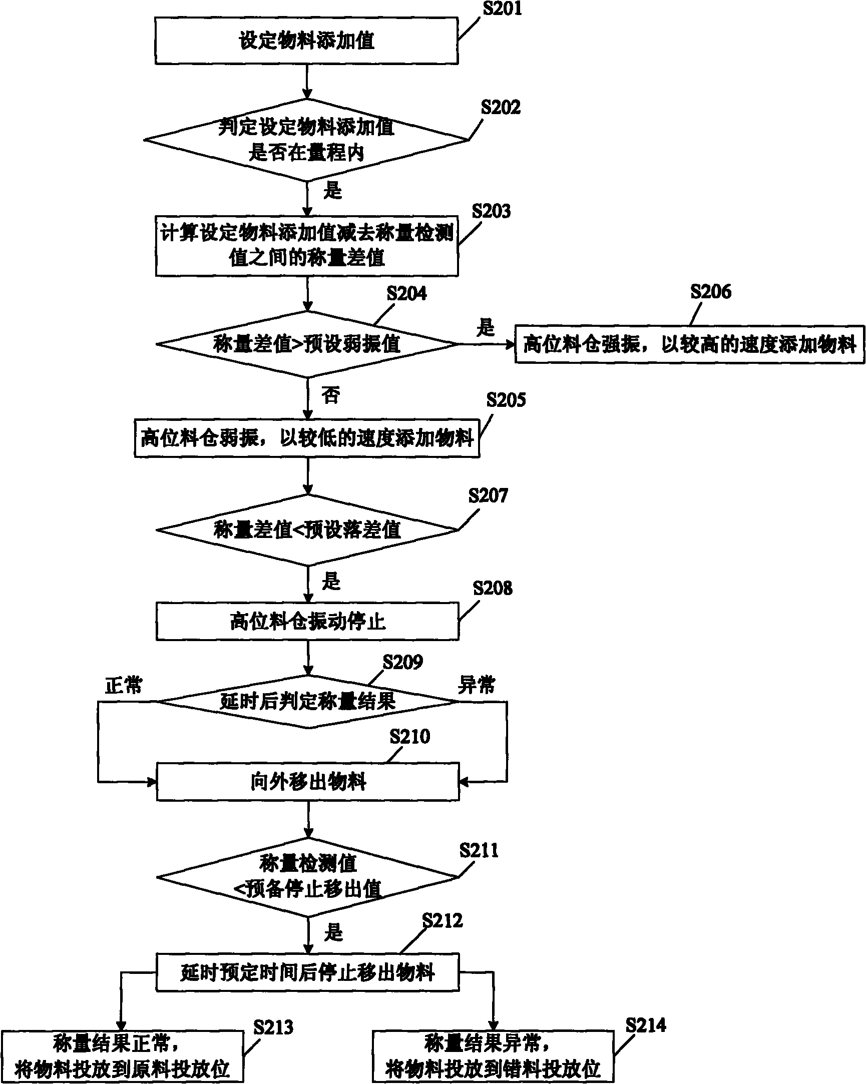
[0052] On the basis of Example 1, as Figure 6 The flow chart of the method for improving the weighing accuracy of the feeding system shown in this implementation, and image 3 Compared with the flow chart of the method for the weighing of the charging system in the prior art shown, the difference only lies in:

[0053] S603: Calculate the weighing difference of the added value of the set material minus the actual value of the current material. Replaces the prior art S203. The purpose of the replacement is to shield the problem of inaccurate weighing caused by the zero point drift, which has been introduced in detail in the first embodiment.

[0054] S611: Judging whether the difference between the weighing detection value minus the original weighing value is less than a predetermined stop-out value. Replaces the prior art S211. The weighing detection value minus the original weighing value is actually the current actual value of the material, the minimum value can reach z...

Embodiment 3

[0101] Such as Figure 7 The schematic diagram of the structure of the device for improving the weighing accuracy of materials shown in this implementation includes:

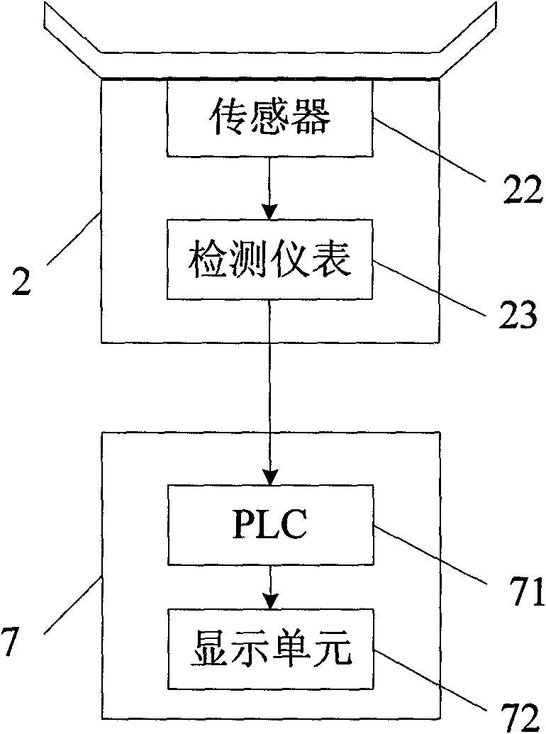
[0102] The preset compensation module 20 whose standard weight is greater than the maximum positive zero drift value and the maximum negative zero drift value of the weighing hopper 2 is installed on the weighing hopper 2 to generate the original weighing value. There is no fixed requirement on the shape of the preset compensation module, which is convenient to pick and place, such as standard weights.

[0103] The control unit 7 includes a calculation unit 701 , a first signal output unit 702 and a second signal output unit 703 .

[0104] The calculation unit 701 is used to calculate the current actual value of the upper material in the weighing hopper 2 according to the original weighing value and the weighing detection value of the weighing hopper 2 . The current actual value can be directly obtained by sub...


PUM


Abstract

The invention discloses a method for improving the weighing precision of a charging system and a device thereof. The method comprises the following steps of: additionally installing a preset compensation module on a weighing hopper to generate an original weighting value, wherein the standard weight of the preset compensation module is larger than the maximum positive zero drift value and the maximum negative zero drift value of the weighing hopper; computing to obtain the current practical value of the material on the weighing hopper according to the original weighting value and the weighing detection value of the weighing hopper; stopping vibrating a high-level stock bin when the current practical value is near to a set material adding value; and discharging the material out of the weighing hopper after the weighing detection value is stable and invariable. The device corresponds to the method. By being additionally provided with the compensation module, the invention simply and skillfully overcomes the problem that the weighing is inaccurate caused by the zero drift, improves the weighing precision of the charging system, and can not increase the production cost.

Description

technical field [0001] The invention relates to a feeding system, in particular to a method and a device for improving the weighing accuracy of the feeding system. Background technique [0002] Automatic feeding systems are widely used in various industries. Taking the metallurgical industry as an example, in order to obtain high-performance alloys, it is often necessary to accurately control the addition ratio of various materials. Such as figure 1 The schematic diagram of the feeding system in the alloy production is shown. The material is added from the high-level silo 1 to the weighing hopper 2 for weighing. After the weighing is completed, the material is transported to the rotary launder 4 by the belt conveyor 3. If the weighing is normal, Then put the material into the raw material placement position 5, if the weighing is abnormal, then put the material into the wrong material placement position 6. The key of the whole feeding system is whether the weighing result o...

Claims


Application Information

Patent Timeline
IPC IPC(8): G01G23/01
Inventor 王昌才徐锡康宋景喆董骏周利华
Owner BAOSHAN IRON & STEEL CO LTD
Why Eureka
Try Eureka