Waveguide slot array antenna apparatus

A technology of slot array antenna and waveguide, which is applied in the direction of leaky waveguide antenna, linear waveguide feeding array, slot antenna, etc., can solve the problems of no enlightenment, no disclosure, etc.

Inactive Publication Date: 2011-02-02
MITSUBISHI ELECTRIC CORP
View PDF6 Cites 17 Cited by
  • Summary
  • Abstract
  • Description
  • Claims
  • Application Information

AI Technical Summary

Problems solved by technology

[0004] In Patent Document 1, although the arrangement position of the slit and the inclination angle of the slit ar

Method used


Image

  • Waveguide slot array antenna apparatus
  • Waveguide slot array antenna apparatus
  • Waveguide slot array antenna apparatus

Examples


Embodiment approach 1

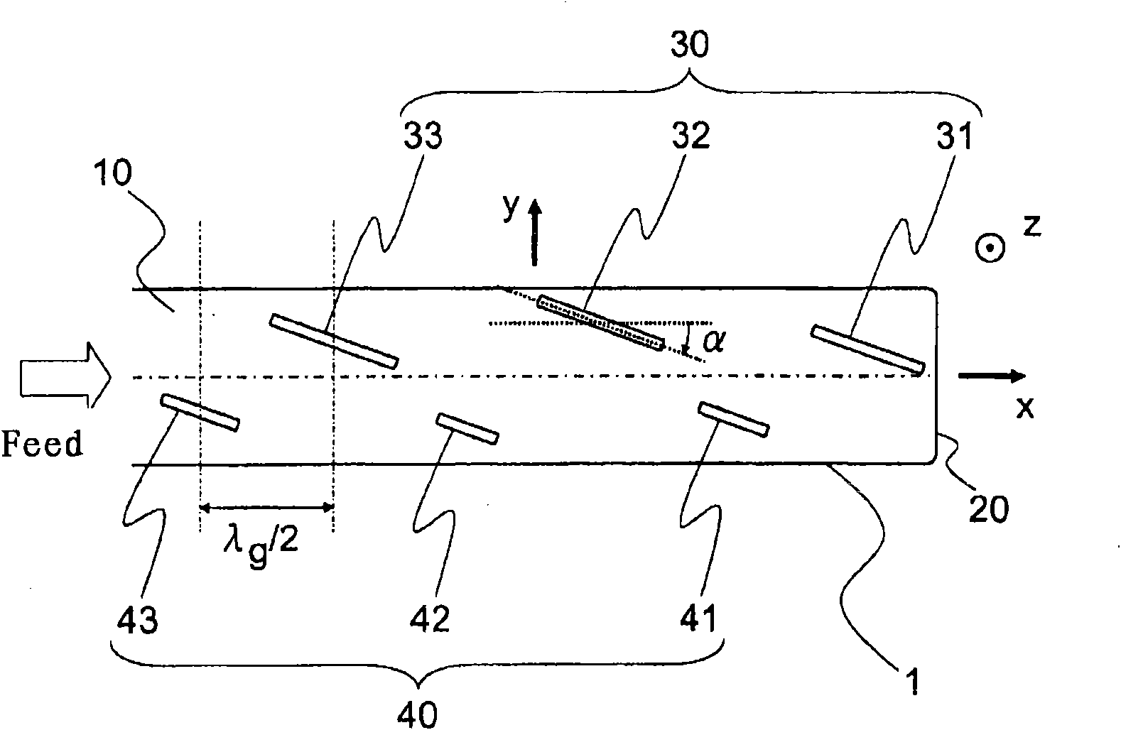
[0033] figure 1 It is a front view showing the wide surface side where the slot is provided of the waveguide slot array antenna device according to Embodiment 1 of the present invention. exist figure 1 Among them, the antenna waveguide 10 as a waveguide slot array antenna is composed of a hollow metal pipe having a rectangular cross section perpendicular to the pipe axis direction. figure 1 The large-width surface shown is a surface corresponding to the long side of the rectangular section, and one of a pair of opposite large-width surfaces is like figure 1 In this way, the slit groups 30, 40 for radiation or incidence are formed. One end of the waveguide 10 in the tube axial direction is blocked by the short-circuit surface 20, and the other end is a power supply port, from which power is supplied (indicated by an arrow Feed). For convenience, the direction of the tube axis of the waveguide 10 is taken as the x direction, the direction perpendicular to the tube axis of...

Embodiment approach 2

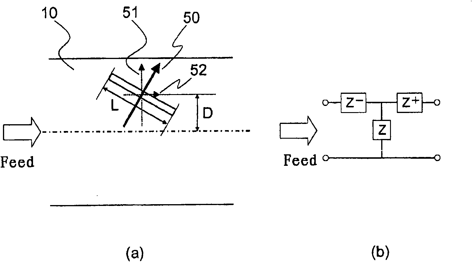
[0048] In the above Embodiment 1, for Figure 5 The distance L between the short-circuit surface 20 of the shown antenna waveguide 10 and the center of the slot 31 adjacent to the short-circuit surface 20 Short The dimensions are not explicitly shown. At the front end of the waveguide 10, if the above L Short If the dimension is about an odd multiple of λf / 4 or an odd multiple of λf / 4, then the front end is open (OPEN) when viewed from the side of the slot 31, and is formed in each of the slots 31-33 or 41-43 in the waveguide 10 A standing wave such that the waveguide width direction component 51 of the current 50 is maximized at the position. This maximizes the power consumption in each slot, that is, the radiation amount from each slot to the space, and high antenna efficiency can be realized.

Embodiment approach 3

[0050] In Embodiment 1 and Embodiment 2 above, the material structure inside the waveguide 10 is not clearly shown. The waveguide 10 can be made of a metal pipe as mentioned above, and the inside is a hollow structure, but it can also be inside the metal pipe of the waveguide 10 like Figure 10 Dielectric material DM is filled as shown. exist Figure 10 In the description, the same reference numerals are given to the same or corresponding parts as those in the above-mentioned embodiment, and description thereof will be omitted (the same applies hereinafter). By filling the waveguide 10 with the dielectric material DM, the effect of shortening the in-tube wavelength of the waveguide according to the permittivity of the dielectric material is obtained. Thereby, the element spacing of the slot can be adjusted, and the degree of freedom in designing the array antenna can be increased.

[0051] In addition, it may not be a hollow metal tube, but such as Figure 11 As shown, on ...


PUM


Abstract

A waveguide slot array antenna apparatus having a polarized wave plane in an oblique direction of a tube axis of a waveguide with proper excitation distribution of an aperture part for electromagnetic wave radiation or incidence. The waveguide slot array antenna apparatus is characterized by having a waveguide slot array antenna composed of a rectangular antenna waveguide whose cross section orthogonal to a tube axis is rectangular, wherein the antenna waveguide has a power feeding port at one end side in the tube axis direction, while the other end side is short-circuited. At a first wide plane of a pair of wide planes in parallel with the tube axis on the antenna waveguide, a plurality of elongated and rectangular (excluding square) apertures for electromagnetic wave radiation or incidence are arranged at intervals of about lambda g/2 (lambdag is intra-tube wavelength) along the tube axis. Each of the apertures has the same specified angle relative to a center line in parallel with the tube axis of the first wide plane, and adjacent apertures are arranged alternately at opposite positions relative to the center line. Each of the apertures at one side relative to the center line of the first wide plane is longer in length than about lambda f/2 (lambda f is free-space wavelength), while each of the apertures at the other side is shorter than about lambda f/2.

Description

technical field [0001] The present invention relates to a waveguide slot array antenna device, in particular to a waveguide slot array antenna device having a polarization plane in a direction inclined relative to the tube axis of the waveguide. Background technique [0002] A known waveguide slot array antenna is a waveguide slot array antenna formed by alternately arranging a plurality of slots parallel to the tube axis with respect to the centerline of the large-width surface of the waveguide in the direction of the tube axis of the waveguide at an interval of about 1 / 2 the tube wavelength. Since an electric field is formed in the width direction of the slit, the polarization plane of this antenna is a direction perpendicular to the tube axis. [0003] Also, for example, Patent Document 1 discloses a waveguide slot array antenna having a polarization plane in a direction inclined with respect to the tube axis of the waveguide. In this waveguide slot array antenna, the sl...

Claims


Application Information

Patent Timeline
IPC IPC(8): H01Q13/10H01Q13/22
CPCH01Q21/005H01Q21/0043H01Q13/22
Inventor 山口聪高桥徹大塚昌孝宫下裕章
Owner MITSUBISHI ELECTRIC CORP
Why Eureka
Try Eureka