
Method for composite machining of blisk flow passage

An integral blisk and composite machining technology, applied in the field of aero-engines, can solve the problems of narrow tool space in the flow channel area, unsuitable control of the machining process, serious tool wear, etc. The effect of increased durability

Inactive Publication Date: 2012-05-23
SHENYANG LIMING AERO-ENGINE GROUP CORPORATION
View PDF0 Cites 1 Cited by
  • Summary
  • Abstract
  • Description
  • Claims
  • Application Information

AI Technical Summary

Problems solved by technology

The flow passage area of ​​the blisk is composed of free-form surfaces in space, and the blade space in the flow passage area is narrow, and the rigidity of the blade is poor. In the past, the blisk used the conventional method of full-blade slot milling, which caused serious tool wear, poor processing conditions, and poor milling depth. (Ap) can not exceed half of the diameter of the milling cutter. Due to the complex structure of the flow passage area of ​​the blisk parts and the sharp change of the cutter axis, the multi-axis linkage processing method has to be adopted, and the processing process is not suitable for control

Method used


Image

  • Method for composite machining of blisk flow passage
  • Method for composite machining of blisk flow passage
  • Method for composite machining of blisk flow passage

Examples


Embodiment Construction

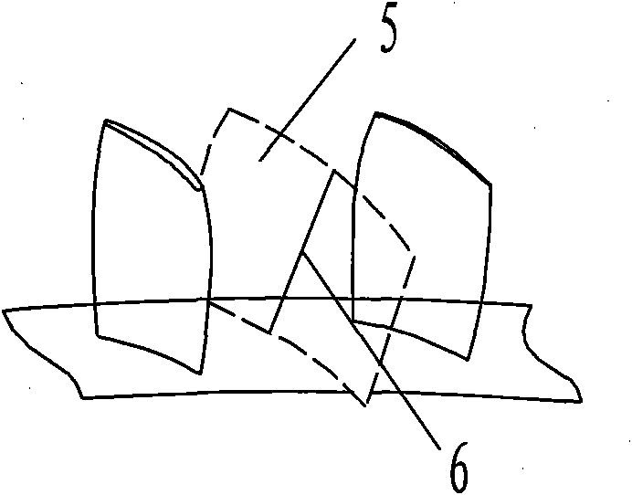
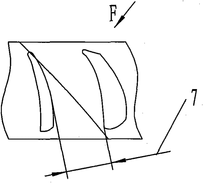
[0063] Such as image 3 with Figure 4 As shown, a compressor blisk is processed, the blisk is composed of a disc and blades, the material is titanium alloy, the blade length = 60mm, the blade width = 50mm, the minimum blade distance = 10mm, and the minimum machining allowance is 1mm.

[0064] According to a method for compound processing of the overall blisk flow channel of the present invention, the specific processing steps are as follows:

[0065] Step 1: Division of processing areas:

[0066] 1. Tool diameter D=10×2=20mm.

[0067] 2. Airfoil safety distance=1+0.2=1.2mm.

[0068] 3. Airfoil safety clearance = 1mm.

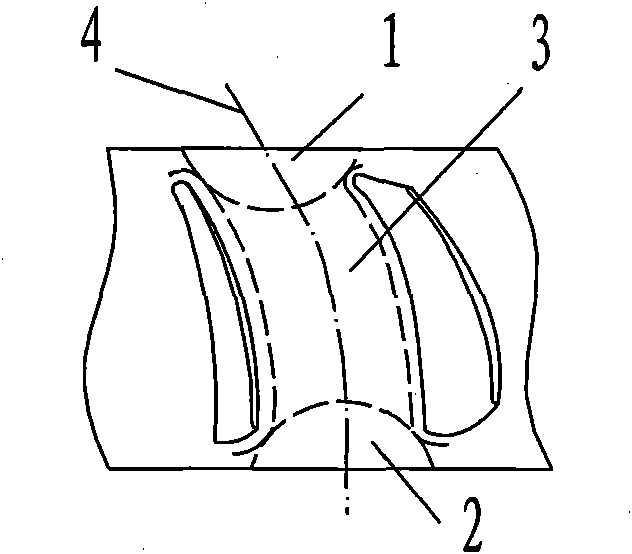
[0069] 4. Determine the triangular area: such as figure 1 As shown, using the CAD model, on the vertical projection plane,

[0070] (1) Determine the edge projection contour line of the leaf back of the adjacent blade and the leaf pot;

[0071] (2) Considering the machining allowance of the rough opening channel, the most edge contour line area is offset...


PUM


Abstract

The invention belongs to the technical field of aircraft engines, and discloses a method for the composite machining of a blisk flow passage. The method is a numerical control machining method of selecting the adaptive machining strategy based on regional characteristics. The method comprises the following steps of: (1) dividing a machining region; and (2) selecting the adaptive numerical controlmachining strategy based on the regional characteristics. In the method, a rough slotting numerical control machining method of combining milling, drilling milling and slotting milling of a cycloid is adopted, so that a medial cambered surface is approximate to a curved surface of a blade profile, and the boundary contour and the optimal cutter-axis vector of a rough machining region in a channelare determined. The method has the advantages that the machining method of region division and cutting-in changing enhances the rigidity and machining stability of blades; a process method of combining the milling and slotting milling of the cycloid improves the durability of cutters and the removal rate of materials; and the vibration phenomenon in the rough machining process is prevented effectively, the cutting force is reduced, the movement space of the cutters is expanded farthest, and the machining efficiency is improved.

Description

technical field [0001] The invention belongs to the technical field of aero-engines, and is a numerically controlled machining method based on regional characteristics to select an adaptive machining strategy, which can be used for the processing of industrial products such as blisks and impellers, and particularly relates to a method for composite processing of flow channels of blisks . Background technique [0002] The processing of blisk parts from forging blanks to final parts requires removal of a large amount of excess material. The flow passage area of ​​the blisk is composed of free-form surfaces in space, and the blade space in the flow passage area is narrow, and the rigidity of the blade is poor. In the past, the blisk used the conventional method of full-blade slot milling, which caused serious tool wear, poor processing conditions, and poor milling depth. (Ap) cannot exceed half of the diameter of the milling cutter at most. Due to the complex structure of the ...

Claims


Application Information

Patent Timeline
Patent Type & Authority Patents(China)
IPC IPC(8): B23C3/00B23C3/16
Inventor 张森棠李冬梅赵恒吴志新
Owner SHENYANG LIMING AERO-ENGINE GROUP CORPORATION
Learn More