
Steel pipe lifting carrier roller device

A technology for lifting brackets and steel pipes, which is applied in the direction of lifting devices, lifting frames, roller tables, etc., can solve problems such as inability to land on the roller frame, swing left and right at the suspended section of steel pipes, and production accidents, so as to improve production efficiency, improve operating efficiency, and avoid The effect of spray quality

Inactive Publication Date: 2011-02-09
浙江龙驰防腐技术有限公司
View PDF5 Cites 16 Cited by
  • Summary
  • Abstract
  • Description
  • Claims
  • Application Information

AI Technical Summary

Problems solved by technology

In this way, when the steel pipe travels in the above-mentioned systems, there must be a suspended section, and this part of the suspended steel pipe will sink under the action of gravity, so that the vertical height of the front end of the steel pipe is lower than the height of the roller frame installed downstream between the systems. As a result, the steel pipe cannot travel normally on the downstream roller frame
In addition, due to the length of large steel pipes ranging from 12 to 90 meters, when they move on the roller frame group of the production line, there will inevitably be eccentric movement, causing the suspended section of the steel pipe to swing from side to side, and it is also impossible to safely and stably move on the downstream rollers. landing
Obviously, the above two phenomena will affect the production efficiency of steel pipe spraying and the spraying quality of the surface, and even production accidents will occur in serious cases.

Method used


Image

  • Steel pipe lifting carrier roller device
  • Steel pipe lifting carrier roller device
  • Steel pipe lifting carrier roller device

Examples


Embodiment Construction

[0026] The present invention will be further described in detail below in conjunction with the accompanying drawings and embodiments.

[0027] This embodiment is a detailed description of the automatic lifting roller device for steel pipes in combination with the operation of large steel pipes on the automatic coating production line.

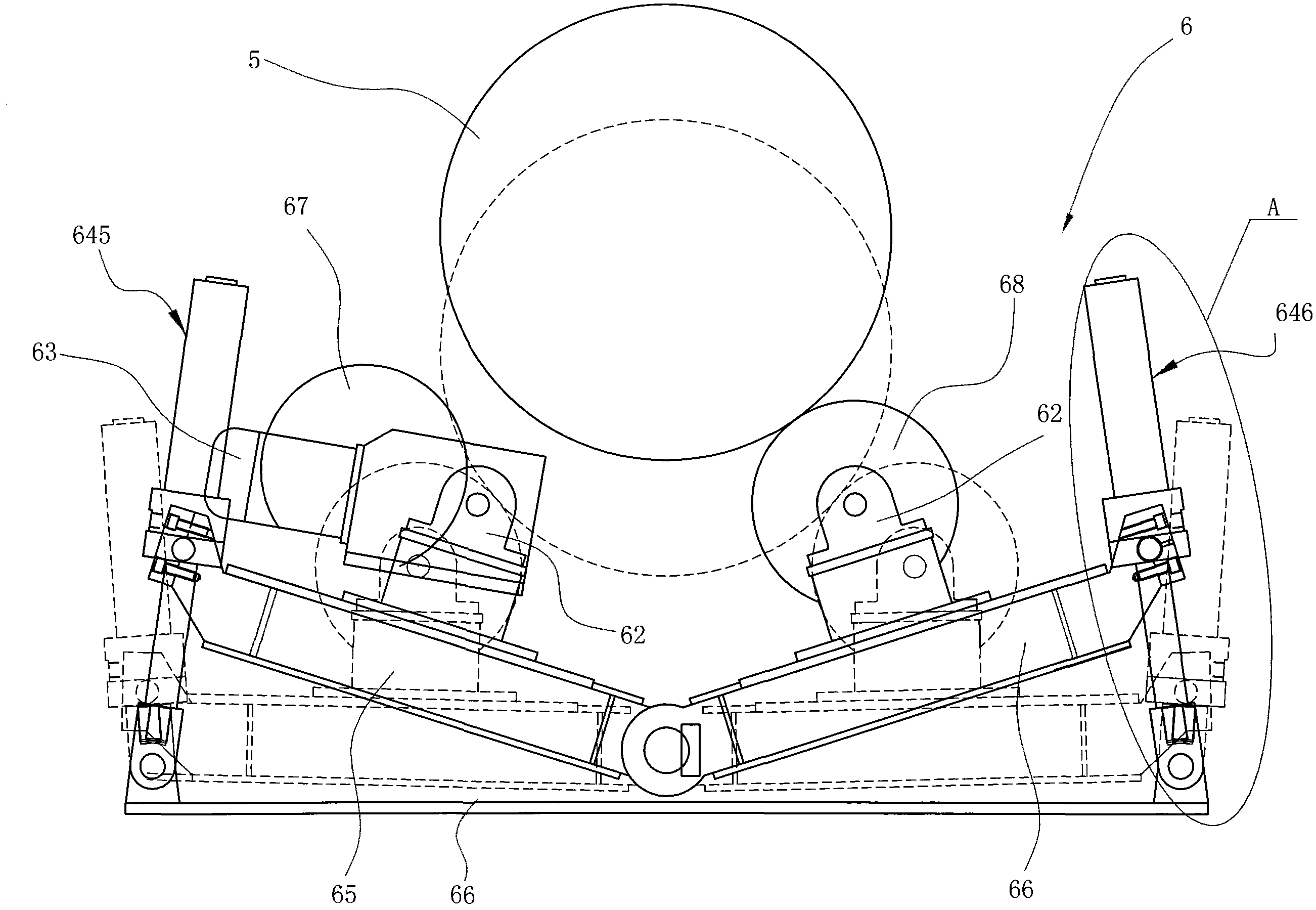
[0028] Such as figure 1 As shown, according to the running route of the steel pipe, the large-scale steel pipe automatic coating production line includes a preheating room 1, a painting room 2 and a drying room 3 in sequence. The distance between the drying room and the drying room is very small, so there is no transmission mechanism between the two. The transmission mechanism in this embodiment adopts a roller frame group, such as figure 1 As shown, the production line is provided with three groups of roller frames from front to back, that is, the first roller frame group 41 , the second roller frame group 42 and the third roller frame group...


PUM


Abstract

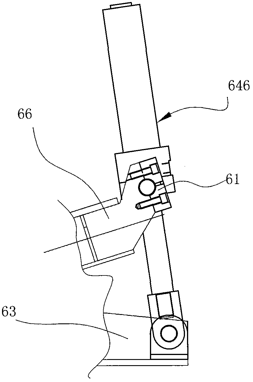
The invention relates to a steel pipe lifting carrier roller device arranged on a production line for conveying steel pipes. The steel pipe lifting carrier roller device comprises a first carrier roller and a second carrier roller which support the steel pipes, wherein the first carrier roller and the second carrier roller are respectively rotationally arranged on a first lifting body and a second lifting body; and the first lifting body and the second lifting body are connected with a first motor through transmission mechanisms. Compared with the prior art, the invention can effectively solve the problem that the steel pipes can not normally advance because a suspension segment declines in the advancing process of the steel pipes; particularly, the steel pipe lifting carrier roller device supports the steel pipes and then automatically supports the steel pipes to a needed height by adopting a first oscillating arm and a second oscillating arm as the lifting bodies and a first oil cylinder and a second oil cylinder as driving parts and a matched hydraulic transmission system and realizes the automatic lifting of the carrier rollers by utilizing a sensor and a limit switch, thereby greatly reducing the operation of operators and enhancing the work efficiency; and in addition, the invention prevents the defects of spraying quality, safety accidents, and the like which are caused by the suspension of the steel pipes, and enhances the production efficiency of production lines, i.e. an automatic spraying production line and the like.

Description

technical field [0001] The invention relates to a supporting device for conveying large steel pipes, in particular to a steel pipe elevating roller device used in occasions such as large steel pipe automatic coating production lines. Background technique [0002] The large-scale steel pipe anti-corrosion coating automatic coating production line includes a steel pipe transmission mechanism, a dehumidification and decontamination machine for removing oil and moisture on the steel pipe surface, an automatic shot blasting machine for removing rust and oxide layers on the steel pipe surface, and a steel pipe to be painted. Preheated preheating oven, spray booth, curing room and cooling room. The steel pipe conveying mechanism described therein usually adopts a plurality of roller frames arranged at intervals between the systems. During the production process, the steel pipe is supported on the roller frame group composed of these roller frames, and is conveyed through each roll...

Claims


Application Information

Patent Timeline
IPC IPC(8): B65G13/00B66F7/00
Inventor 史岳明范列朋熊信勇李俊良
Owner 浙江龙驰防腐技术有限公司
Learn More