LED tube

A technology of LED lamp tube and tube body, which is applied in the direction of electric lamp circuit layout, damage prevention measures for lighting devices, cooling/heating devices for lighting devices, etc. Solve problems such as light decay, achieve the effect of strengthening the structural life, ensuring the lighting effect, and the ideal heat dissipation effect

Inactive Publication Date: 2011-02-09
ZHONGSHAN WEIQIANG TECH
View PDF1 Cites 5 Cited by
  • Summary
  • Abstract
  • Description
  • Claims
  • Application Information

AI Technical Summary

Problems solved by technology

[0004] The sockets at both ends of the LED light tube can fix the light tube to the standard lamp holder and get the power from the lamp holder. Therefore, in the use state, the LED light tube is horizontally mounted and fixed between the two lamp holders. Only the two ends of the tube body are fixedly supported by the lamp holder, so that the middle part of the tube body is affected by its own weight and has a downward stress; in this state, for the first type of LED lamp tube in the above structural scheme, during its working process, the plastic The tube body will gradually soften when heated, combined with gravity, the middle part of the tube body will be affected and produce slight deformation, so after long-term use of the lamp tube, the middle part will bend downward obviously, affecting the appearance of the lamp tube, and it is not easy to use. No matter how safe; for the second type of LED light tube in the above structural scheme, due to the effect of the aluminum profile combined on the back of the tube body, in addition to having a better heat dissipation effect, it is supported by the aluminum profile on the back when it is working and heated. , the tube body is not easily deformed by heat, can maintain a relatively long-term beautiful appearance, and the installation structure is also stronger. However, because this type of LED tube uses more aluminum, it will greatly increase the manufacturing cost, resulting in expensive products, which are lacking in the market. Moreover, fixing the circuit board through aluminum profiles will make the position of the circuit board in the tube body closer to the front of the tube, thus reducing the irradiation angle of the lamp tube and reducing the lighting effect
[0005] As mentioned above, the LED lamp tube is installed on the lamp holder by the plug-in ends at both ends of the tube body for fixing and taking power. The metal terminals of the plug-in end must match the interface of the lamp holder , in order to get electricity normally, which requires that the plug-in terminal must be assembled accurately and have sufficient strength to ensure that it is firmly fixed to the pipe body and will not rotate or shift under a certain torque or external force. The current basic plan is all Adhesive glue is used to bond the plug-in end to the end of the tube body. The disadvantage of this method is that it cannot be disassembled after being glued and fixed, otherwise it will cause damage to the connection relationship. The heat will soften the viscose and reduce the viscous force, which may cause the plug-in end to fall off
[0006] In addition, LED tubes are used in on-site lighting. Generally, the mains power is converted to DC to power the LEDs. In some cases, the frequency of the mains power is unstable, which will affect the current value passing through the LED chip. If If the current through the LED chip is too large, it will cause permanent light decay to the LED chip, resulting in a permanent reduction in the brightness of the LED tube, which cannot meet the required light intensity requirements.

Method used


Image

  • LED tube
  • LED tube
  • LED tube

Examples


Embodiment Construction

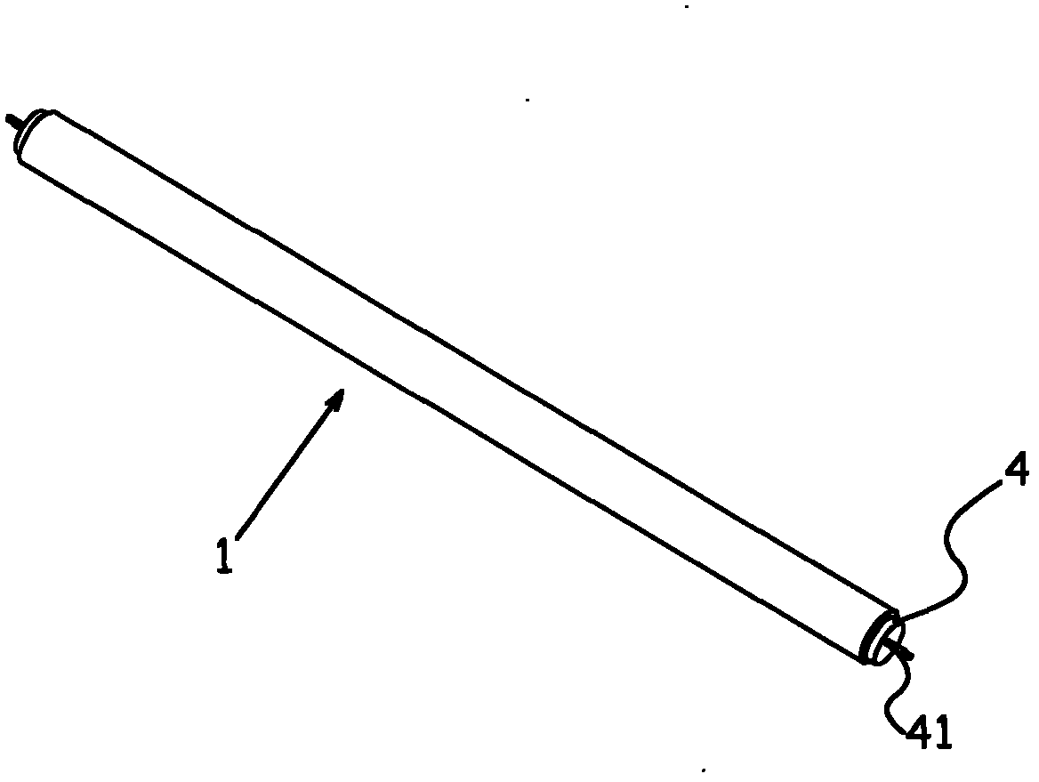
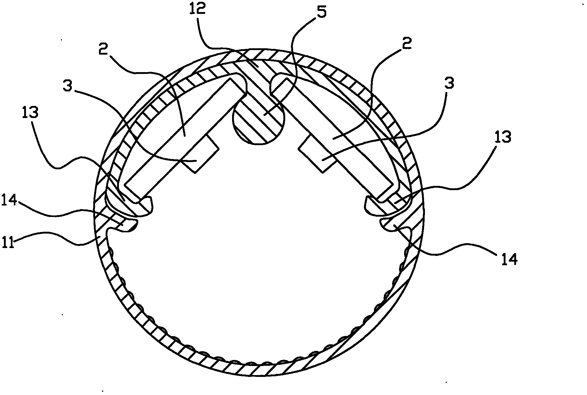
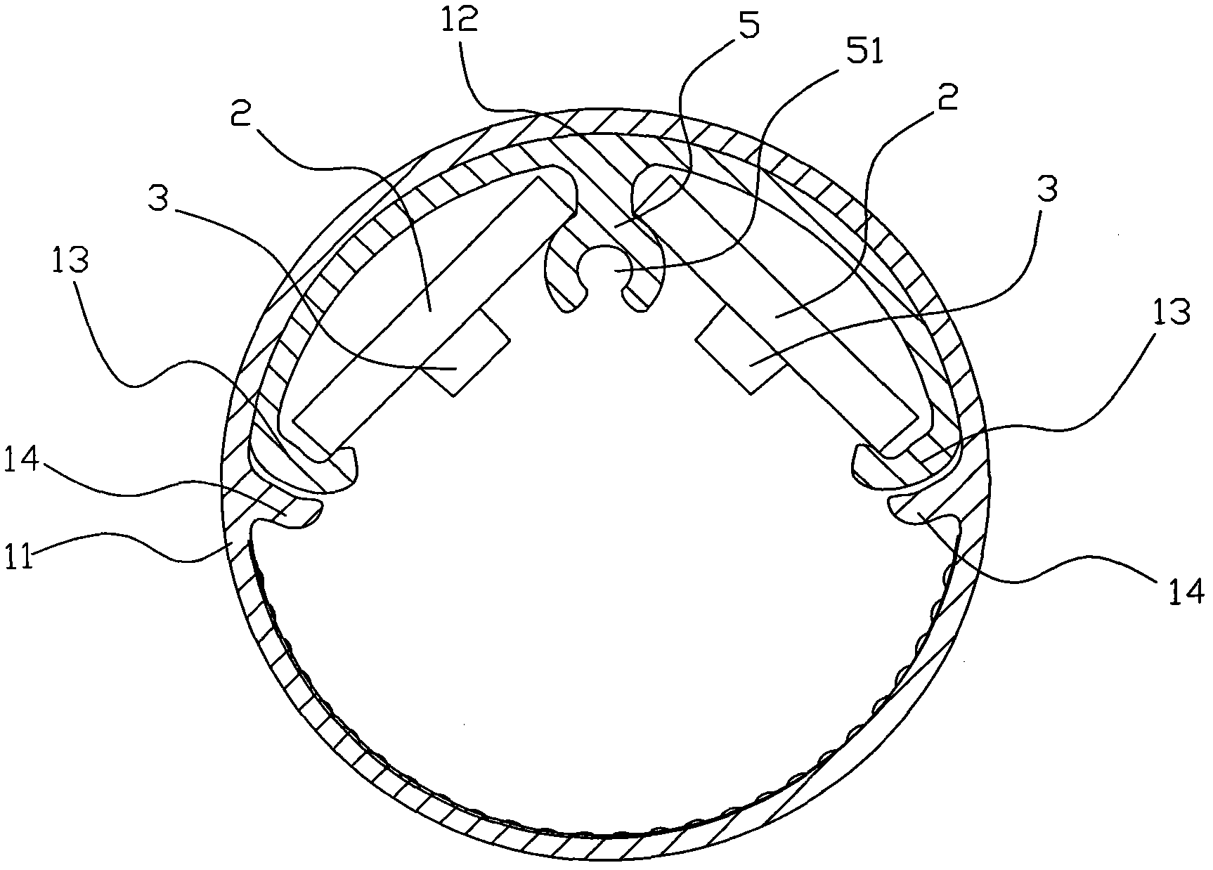
[0038] Such as figure 1 and figure 2 The shown LED lamp tube includes a tube body 1, a circuit board 2 installed in the tube body 1, a light-emitting diode module 3 arranged on the circuit board 2, and an electrical plug group is provided at both ends of the tube body 1. 11, wherein the circuit board 2 is connected to the electrical plug-in group 4, the electrical plug-in group adopts a standard double-pin structure, and has two convex plug-in terminals 41, wherein the two convex plug-in terminals 41 are connected in a short-circuit state, It becomes a standard plug terminal that can be plugged into a traditional fluorescent lamp socket to connect to an external power source to obtain electricity.

[0039] The tube body 1 is mainly composed of an outer tube body 11 and an inner arc-shaped strip 12, wherein the outer tube body 11 is an integrally formed tube with a hollow chamber. The function of the lens is to expand the luminous angle; the back of the inner curved strip 12...


PUM


Abstract

The invention discloses an LED tube, comprising a tube body, a circuit board arranged in the tube body, a light-emitting diode module arranged on the circuit board, and an electric plug-in assembly arranged at the two ends of the tube body, wherein, the tube body comprises an outer tube body and an inner arc-shaped strip; the outer tube body is an integrated molding tube with a hollow chamber; the backside of the inner arc-shaped strip is fitted with the inner wall of the outer tube body, the right side of the inner arc-shaped strip is provided with at least one group of support positioning ribs composed of two cervical ribs along the length direction; the circuit board is a long strip, the right side of the circuit board is fixed with at least one light-emitting diode modules, and the two sides of the circuit board are clamped through two cervical ribs of the support positioning rib to be fixed on the inner arc-shaped strip. The LED tube has firm assembling structure, is not easy to heat to deform, can form the wholly light emitting of the tube body as the traditional fluorescent tube, and has more outstanding illumination effect.

Description

technical field [0001] The invention relates to an LED lamp, in particular to an LED lamp tube. Background technique [0002] Fluorescent lamps are commonly used lighting fixtures. In recent years, LED lamps have gradually replaced traditional fluorescent lamps and become mainstream lighting lamps due to their advantages in environmental protection, energy saving, long life, and high efficiency. [0003] Due to the structural characteristics of LED lights currently on the market, and considering the characteristics of relatively high heat generation of LEDs, the usual assembly scheme is to install the LED chip on the circuit board, and then install the circuit board in the tube body. The standard plug-in terminals at both ends of the body can be inserted into the lamp socket for lighting work. When the LED emits light, the heat generated is transferred to the tube body through the circuit board and then emitted by the tube body. Functions such as transparent light guide, in...

Claims


Application Information

Patent Timeline
Patent Type & Authority Applications(China)
IPC IPC(8): F21S2/00F21V23/06F21V29/00H05B37/02F21V17/16F21V19/00F21V15/02F21Y101/02
Inventor 李克勤林士乾
Owner ZHONGSHAN WEIQIANG TECH
Why Eureka
Try Eureka