
System and method for inductive charging of portable devices

A portable device and device technology, applied in charging stations for charging mobile devices, preventing/reducing unwanted electric/magnetic influences, exchanging data chargers, etc., can solve the problems of large magnetic cores, low power efficiency of chargers, and Those who can not get the power supply and other problems, to achieve the effect of high power transmission efficiency

Active Publication Date: 2011-02-09
MOJO MOBILITY
View PDF15 Cites 201 Cited by
  • Summary
  • Abstract
  • Description
  • Claims
  • Application Information

AI Technical Summary

Problems solved by technology

However, each of these approaches suffers from poor power transfer due to the fact that most of the power from the primary is not picked up in the receiver, and thus the overall power efficiency of the charger is poor
Additionally, the magnetic cores used for the primary and receiver are often bulky, adding to the overall cost and size of the system and limiting their incorporation into many devices
[0014] Another point to note is that while all of the above devices allow the user to charge the device, they also require either the charging device or the base unit to be electrically connected to a power source such as an electrical outlet or a DC power source
In many cases, such as when traveling, camping, or working in places where power is not available, the user may not have access to such power
However, to date, no device has been provided that is portable and allows for inductive charging of multiple devices with differing power requirements, and that itself can be charged intermittently or occasionally by an external power source or otherwise, or that is self-powered or include your own power supply

Method used


Image

  • System and method for inductive charging of portable devices
  • System and method for inductive charging of portable devices
  • System and method for inductive charging of portable devices

Examples


Embodiment Construction

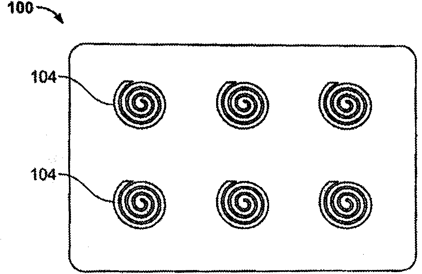
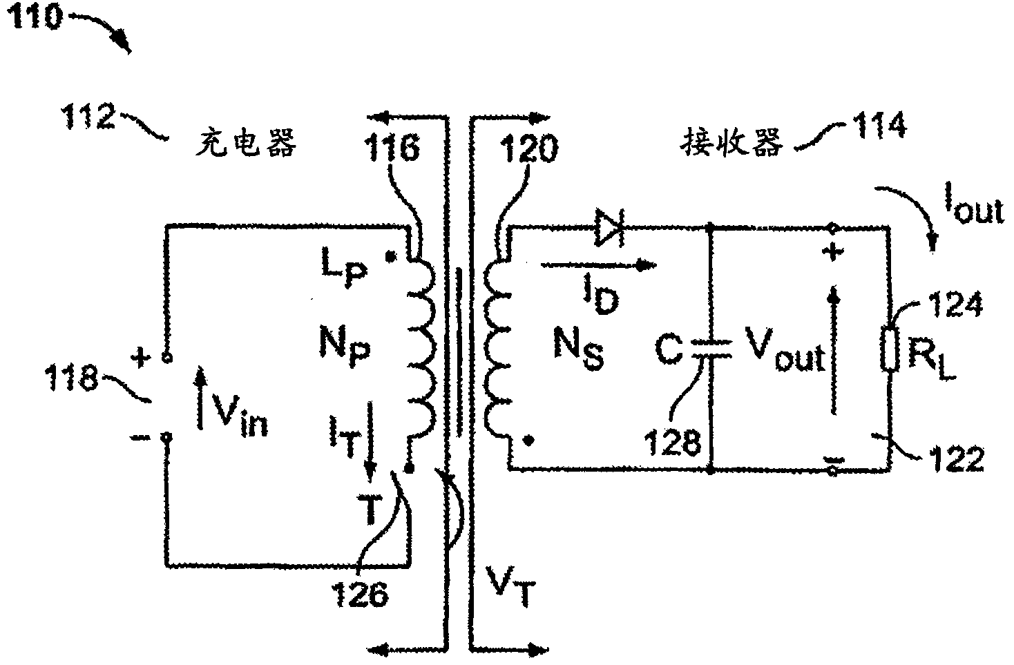
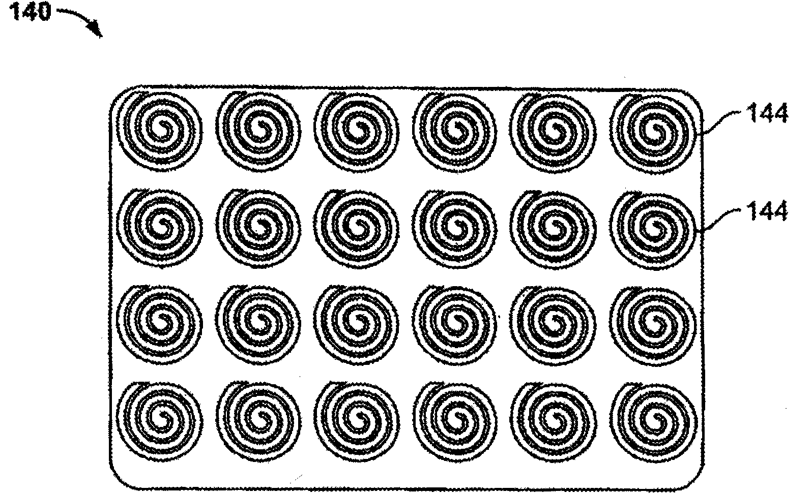
[0093] Portable inductive power supplies, power supply devices or units for powering or charging electrical, electronic, battery operated, mobile, rechargeable batteries and other devices are disclosed herein. According to an embodiment, the system consists of two parts: the first part is a pad or similar base unit containing a primary generating an alternating magnetic field by applying an alternating current to a winding, coil or any type of current-carrying wire. In some embodiments, the pad may also include various signaling, and switching or communication circuits, or means to identify the device to be charged or powered and the presence of the battery. In some embodiments, the pad may also contain multiple coils or sections to charge or power various devices, or to allow charging or powering of devices and batteries placed anywhere on the pad. The second part of the system is the receiver, which includes components for receiving energy from the alternating magnetic field...


PUM


Abstract

A system and method for variable power transfer in an inductive charging or power system. In accordance with an embodiment the system comprises a pad or similar base unit that contains a primary, which creates an alternating magnetic field. A receiver comprises a means for receiving the energy from the alternating magnetic field from the pad and transferring it to a mobile device, battery, or other device. In accordance with various embodiments, additional features can be incorporated into the system to provide greater power transfer efficiency, and to allow the system to be easily modified for applications that have different power requirements. These include variations in the material used to manufacture the primary and / or the receiver coils; modified circuit designs to be used on the primary and / or receiver side; and additional circuits and components that perform specialized tasks, such as mobile device or battery identification, and automatic voltage or power-setting for different devices or batteries.

Description

[0001] Copyright statement [0002] A portion of the disclosure of this patent document contains material protected by copyright. The copyright owner has no objection to the facsimile reproduction by anyone of the patent document or the patent disclosure as it appears in the Patent and Trademark Office's patent literature or collection, but reserves all copyright in all other cases. [0003] priority claim [0004] This application claims priority to US Patent Application 12 / 116,876, filed May 7, 2008, entitled "SYSTEM AND METHODFOR INDUCTIVE CHARGING OF PORTABLE DEVICES," which was filed January 30, 2007 A continuation-in-part of U.S. Patent Application 11 / 669,113, entitled "INDUCTIVE POWER SOURCE AND CHARGING SYSTEM," which claims the U.S. Provisional Patent Application 60 / 763,816, U.S. Provisional Patent Application 60 / 810,262, filed June 1, 2006, entitled "MOBILEDEVICE, CHARGER, AND POWER SUPPLY" , BATTERY, CHARGING SYSTMEM, AND POWER SUPPLY," U.S. Provisional Patent Appl...

Claims


Application Information

Patent Timeline
Patent Type & Authority Applications(China)
IPC IPC(8): H02J7/00
CPCH02J7/025H02J7/0027H02J7/0004H01F5/003H01F38/14H02J7/00036H02J2310/22H02J7/0044H02J7/0013H01F27/363H01F27/366H01F27/361H04W4/80H02J50/10H02J50/005H02J50/90H02J50/12H02J50/80H02J50/70H02J7/00H01F27/36H01F27/2804H02J7/0042
Inventor 阿夫钦·帕托维迈克尔·西尔斯
Owner MOJO MOBILITY
Learn More