Hydraulic pressurization device of grinder roller of vertical grinding mill

A technology of a pressurizing device and a vertical mill, which is applied in grain processing and other directions, can solve the problems of difficulty in achieving precision control of feed rate, damage to mechanical parts and hydraulic valve blocks, overall weight of equipment, and large energy consumption, saving materials. The effect of consuming and arranging space, reducing the load, and reducing the difficulty of space layout

Active Publication Date: 2013-05-08
JIANGSU HENGYUAN INT ENG CO LTD
View PDF3 Cites 0 Cited by
  • Summary
  • Abstract
  • Description
  • Claims
  • Application Information

AI Technical Summary

Problems solved by technology

[0006] In addition, the structure size of the upper rocker arm 12 and the lower rocker arm 11 in the aforementioned structure is large, and consumes a lot of materials, so that the overall weight and energy consumption of the equipment are also large.
In addition, the principle of leverage is used to achieve pressurization. Generally, the length of the lower rocker arm 11 is longer than the length of the upper rocker arm 12, so as to obtain greater working pressure. The problem brought about is that the feed rate is difficult to achieve precision control. Under uniform conditions, it can form a destructive reaction force to the system, damaging mechanical parts and hydraulic valve blocks

Method used


Image

  • Hydraulic pressurization device of grinder roller of vertical grinding mill
  • Hydraulic pressurization device of grinder roller of vertical grinding mill
  • Hydraulic pressurization device of grinder roller of vertical grinding mill

Examples


Embodiment Construction

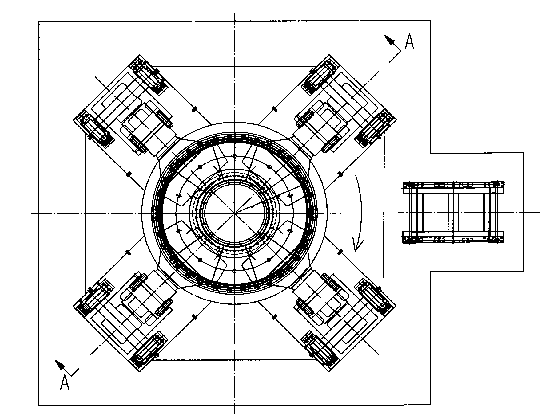
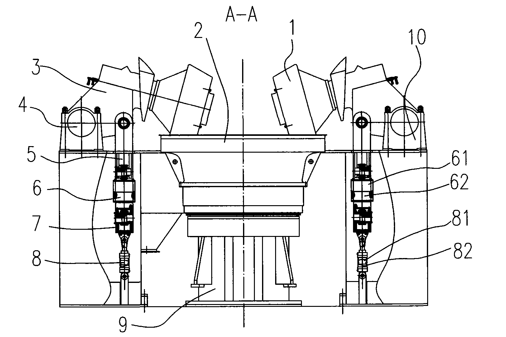
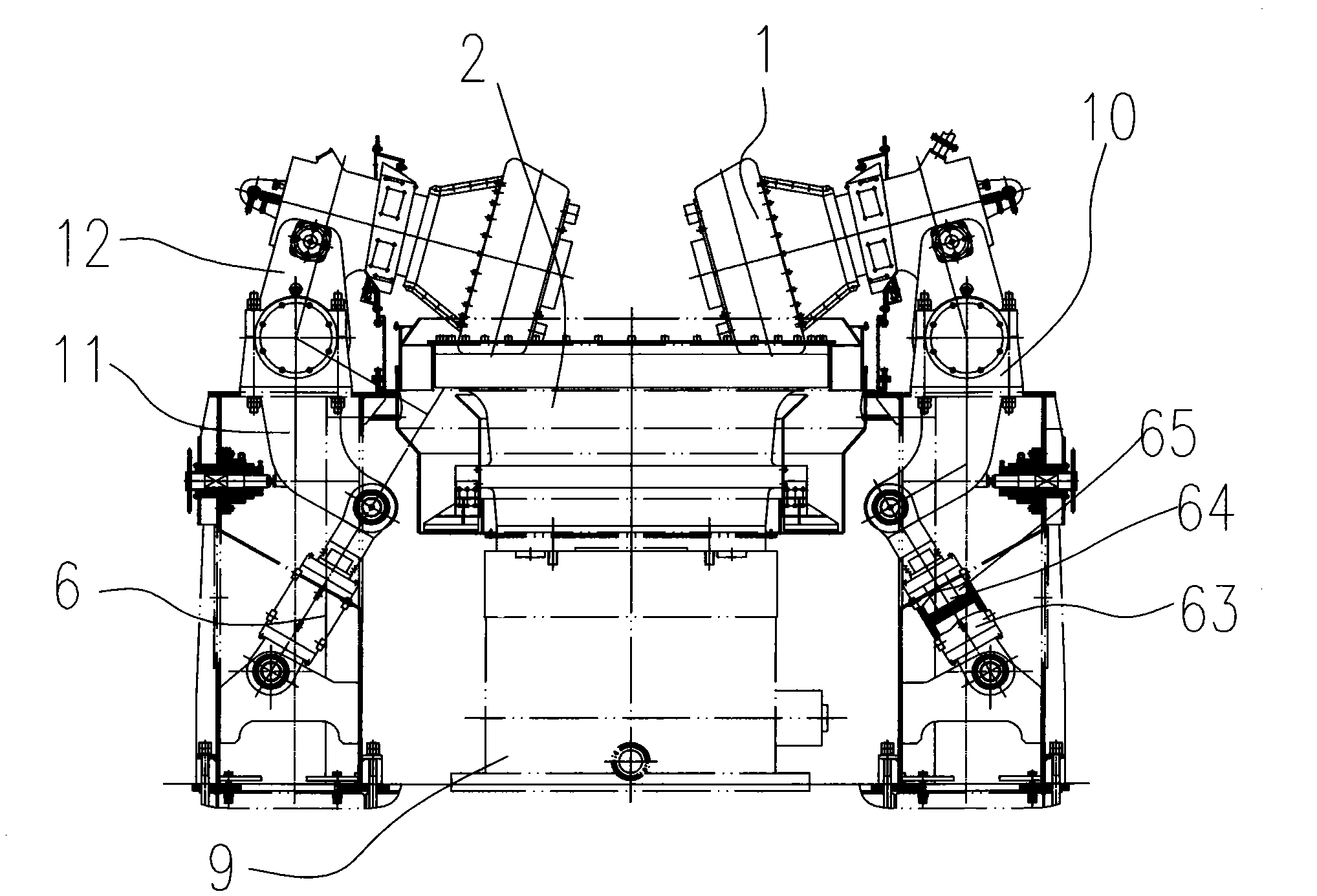
[0023] Such as figure 1 , 2 As shown, the vertical mill of the present invention includes a grinding head 3, a grinding disc 2 horizontally movably connected to a machine body 9; the grinding roller 1 is in the shape of a conical platform, and is movably connected to the front end surface of the grinding head 3. The grinding head 3 is rotated The pin 4 is connected to the machine body 9 so that the conical roller surface of the grinding roller 1 is located above the grinding disc 2.

[0024] It also includes a double-feed transmission device; the double-feed transmission device includes a pressurized cylinder 6, a buffer cylinder 8, a bottom tie rod, a top tie rod 5, and a coupling assembly 7. 7) A coaxial integrated structure is formed with the pressure cylinder 6 on top and the buffer cylinder 8 on the bottom. The lower part of the buffer cylinder 8 is connected to the body 9 through a bottom tie rod; the upper part of the pressure cylinder 6 is fixedly connected to the lower e...


PUM


Abstract

The invention discloses a hydraulic pressurization device of a grinder roller of a vertical grinding mill, which relates to the improvement on the pressurization device of a grinder roller of a vertical grinding mill and has the advantages of high control precision, high energy conversion and utilization rate and lighter structure. The hydraulic pressurization device comprises a grinding head, a millstone and a double-feed hydraulic device; the grinder roller is in a circular truncated cone shape and movably connected to the front end face of the grinding head which is connected to a mill body through a rotation pin so as to ensure that the conical roller surface of the grinding roller is located above the millstone; the double-feed hydraulic device comprises a pressurization oil cylinder, a buffering oil cylinder, a bottom draw bar and a top draw bar, the pressurization oil cylinder and the buffering oil cylinder form a coaxial structure with the pressurization oil cylinder on the upper part and the buffering oil cylinder on the lower part through a connector, and the lower part of the buffering oil cylinder is connected onto the mill body through the bottom draw rod; the upper part of the pressurization oil cylinder is fixedly connected with the lower end of the top draw rod, and the upper end of the top draw rod is articulated with the bottom of the middle section of the grinding head; and the bottom of the rear section of the grinding head is connected onto the mill body through the rotation pin. Under the same pressure, the diameter of a hydraulic cylinder is decreased, or under the same diameter, the pressure is reduced.

Description

Technical field [0001] The invention relates to an improvement of a roller pressing device of a vertical mill. Background technique [0002] With the continuous development of cement production technology and the increasing size of the cement industry, it has become a trend for roller vertical mills to be widely used in the cement industry. The reason why roller vertical mills are generally recognized is mainly because of their working principle, grinding Mechanism, equipment structure, system manufacturability and other aspects have their own unique advantages; for example, its process system is simple, easy to control, can use a large number of preheater kiln exhaust gas, and save energy consumption, high grinding efficiency, and ball mill Compared with the system, it has a small footprint, simple process system, low capital investment, low energy consumption, low metal consumption and low noise. The weight of both the system and the single machine is small compared with the ba...

Claims


Application Information

Patent Timeline
Patent Type & Authority Patents(China)
IPC IPC(8): B02C15/00
Inventor 郭宇霆徐会龙蔡亚宁
Owner JIANGSU HENGYUAN INT ENG CO LTD
Why Eureka
Try Eureka