Distributing and discharging device for centrifuge

A technology of unloading device and centrifuge, which is applied to centrifuges and other directions, can solve the problems of high cloth requirements, complex structure and large size, and achieve the effect of uniform cloth and convenient installation.

Active Publication Date: 2011-02-16
JIANGSU PEONY CENTRIFUGE MFG
View PDF5 Cites 17 Cited by
  • Summary
  • Abstract
  • Description
  • Claims
  • Application Information

AI Technical Summary

Problems solved by technology

The fly in the ointment is that due to the vertical structure, the requirements for the material distribution in the drum are relatively high. Even if the material is fed at a low speed, if the material distribution is uneven, it will cause great vibration during high-speed dehyd

Method used


Image

  • Distributing and discharging device for centrifuge
  • Distributing and discharging device for centrifuge
  • Distributing and discharging device for centrifuge

Examples


Embodiment Construction

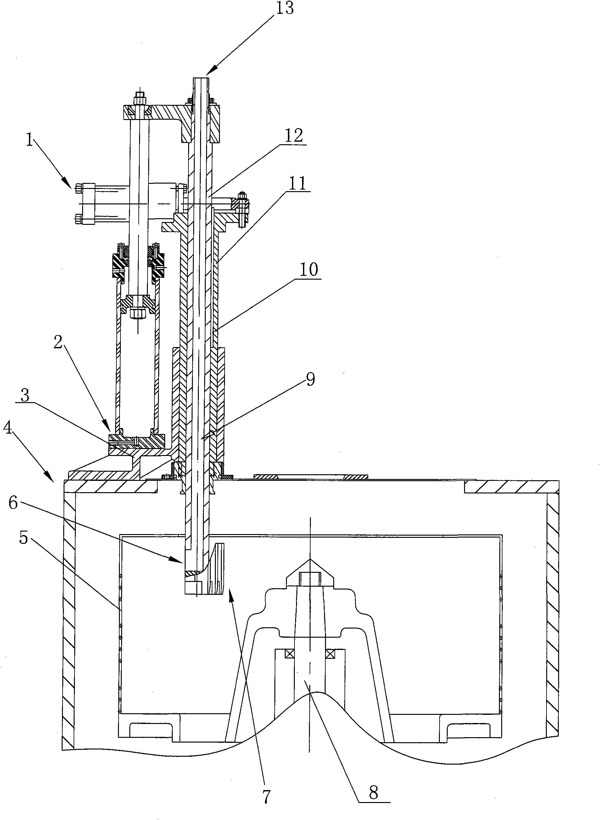
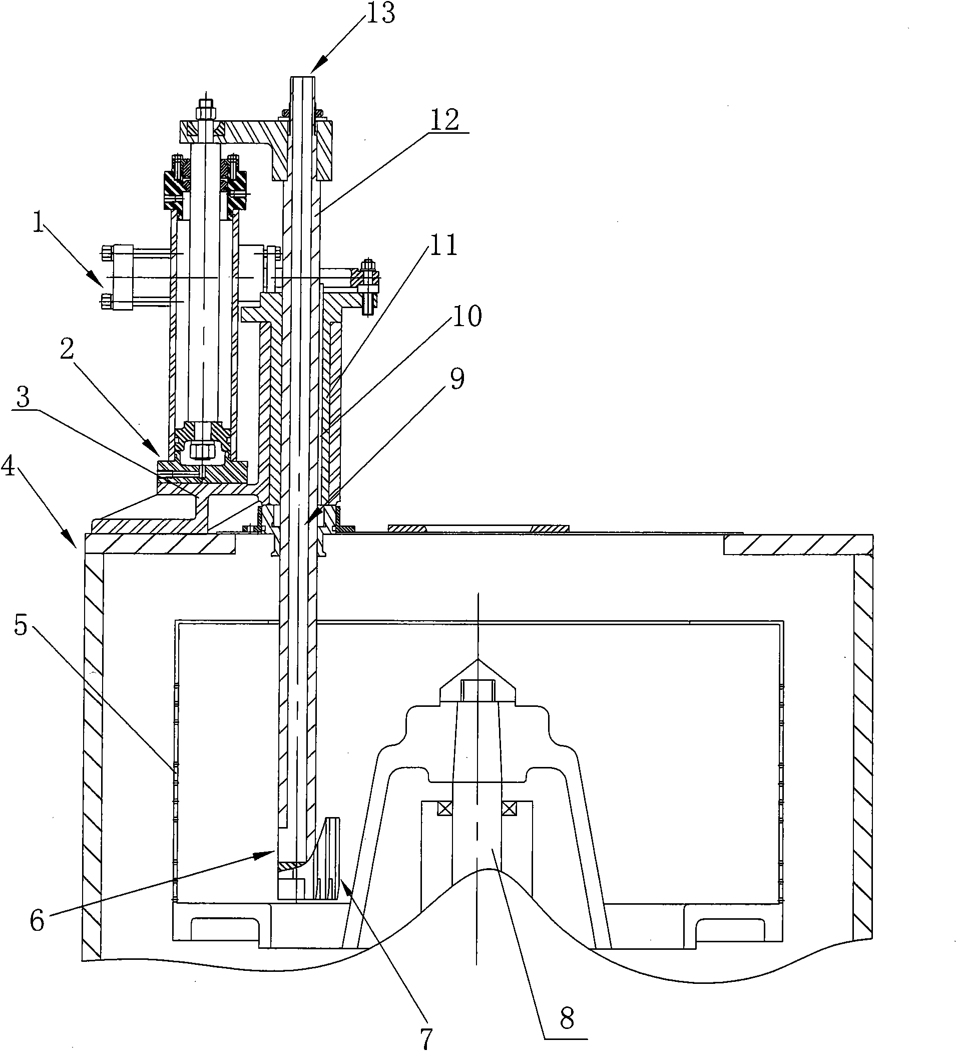
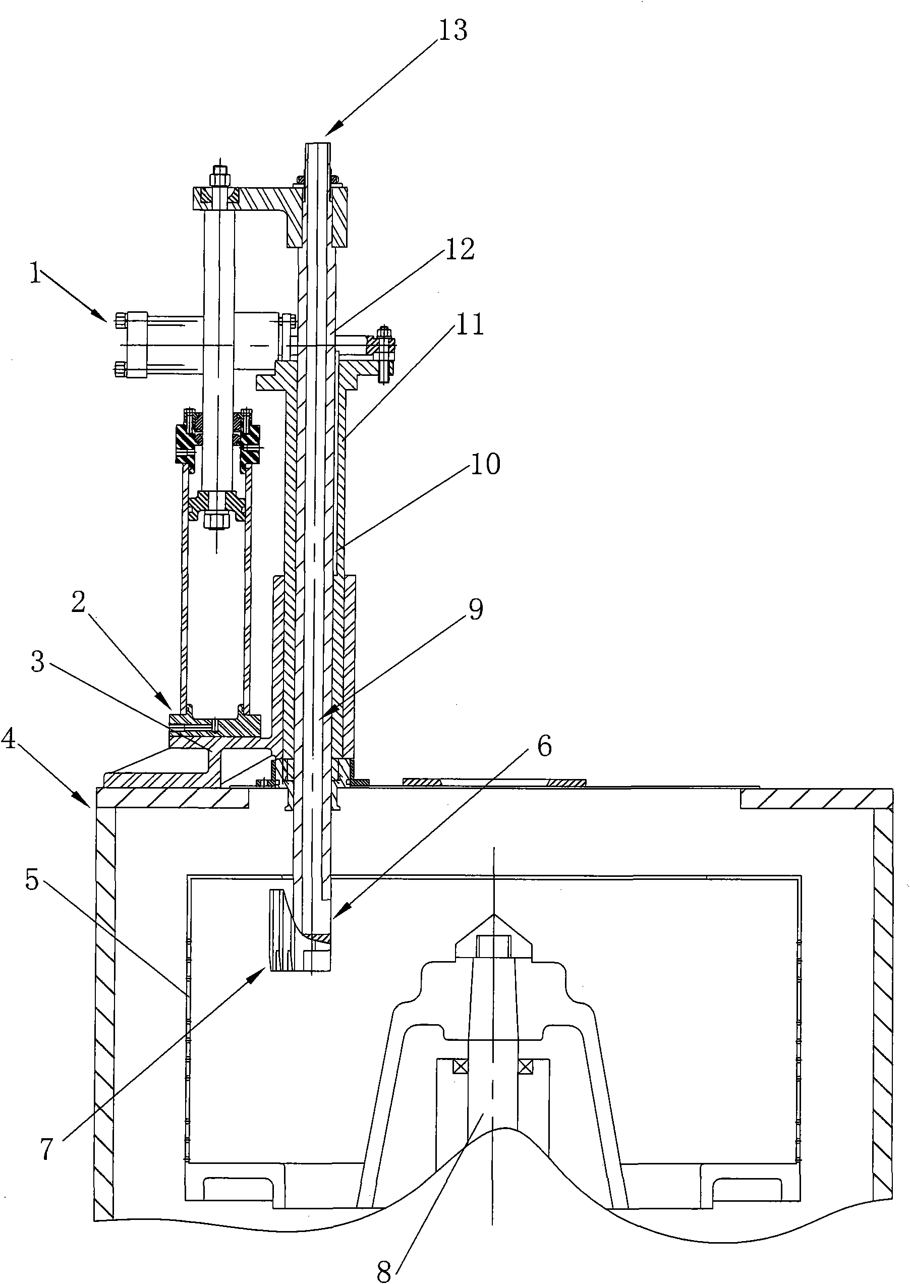
[0021] The present invention will be further described below in conjunction with the embodiment shown in accompanying drawing:

[0022] see Figure 1-3 A distributing and unloading device for a centrifuge is shown, including a casing 4, a machine base arranged on the casing 4, a drum 5 arranged in the casing 4, and a feed pipe 12 inserted into the casing 4 And be fixed on the scraper blade 7 on the feed pipe 12; Feed pipe 12 comprises the feed opening 13 that is positioned at the outside casing 4 and is positioned at the cloth opening 6 in casing 4; An axially moving lifting drive device (can be embodied as a lifting power cylinder) 2, a rotating drive device that drives the feed pipe 12 to rotate around its own axis (shown as a rotating power cylinder) 1, a connecting casing 4, and a lifting drive device 2 and the support seat 3 of the rotary drive device 1; the feed pipe 12 passes through the support seat 3 and the casing 4 and is provided with a through sliding chamber 9; ...


PUM


Abstract

The invention relates to a distributing and discharging device for a centrifuge. The device comprises a shell, a base, a drum, a feeding pipe and a scraper blade; the feeding pipe comprises a feeding hole outside the shell and a distributing hole in the shell; the base comprises a lifting drive device for driving the feeding pipe to move along the axial direction thereof, a rotating drive device for driving the feeding pipe to rotate along the axis thereof, and a supporting seat for connecting the shell, the lifting drive device and the rotating drive device; the scraper blade is positioned on the outer side of the distributing hole of the feeding pipe, and the edge of the scraper blade is staggered with the distributing hole in the circumferential direction encircling the axis of the feeding pipe; and when the feeding pipe rotates to the edge of the scraper blade and faces the inner wall of the drum, the distributing hole faces a main shaft. By adopting the structure, the distributing range can be controlled so that the distribution is uniform; and the distributing device and the scraper device are integrated so as to facilitate the operations such as installation, repair, later maintenance and the like and quickly, repeatedly and automatically distribute and scrape materials.

Description

technical field [0001] The invention relates to a cloth unloading device for a centrifuge. Background technique [0002] A centrifuge is a device that uses the principle of centrifugal separation to separate the suspended material into solid and liquid. A centrifuge has a cylinder, called a bowl, that rotates at high speed about its own axis, usually driven by an electric motor. After the suspension (or emulsion) is added to the drum, it is quickly driven to rotate at the same speed as the drum, and the components are separated under the action of centrifugal force and discharged separately. Generally, the higher the drum speed, the better the separation. [0003] The scraper unloading centrifuge is a major improvement to the traditional centrifuge. By using the scraper to scrape the filter residue from the drum, the unloading process becomes very convenient, thereby improving production efficiency and reducing labor intensity. ; And it also avoids the pollution and scatt...

Claims


Application Information

Patent Timeline
IPC IPC(8): B04B11/02B04B11/08
Inventor 顾济林张威顾坤一杨善成
Owner JIANGSU PEONY CENTRIFUGE MFG
Why Eureka
Try Eureka