

Silicon rod glue joint machine with single clamping bracket
A technology of clamping mechanism and silicon rod, which is applied in the direction of manufacturing tools, stone processing equipment, working accessories, etc., can solve the problems of difficult normal production, uneconomical, waste of energy, etc., and achieve the reduction of adjustment distance, simple structure, and convenient operation Effect
- Summary
- Abstract
- Description
- Claims
- Application Information
AI Technical Summary
Problems solved by technology
Method used
Image

Examples
Embodiment Construction
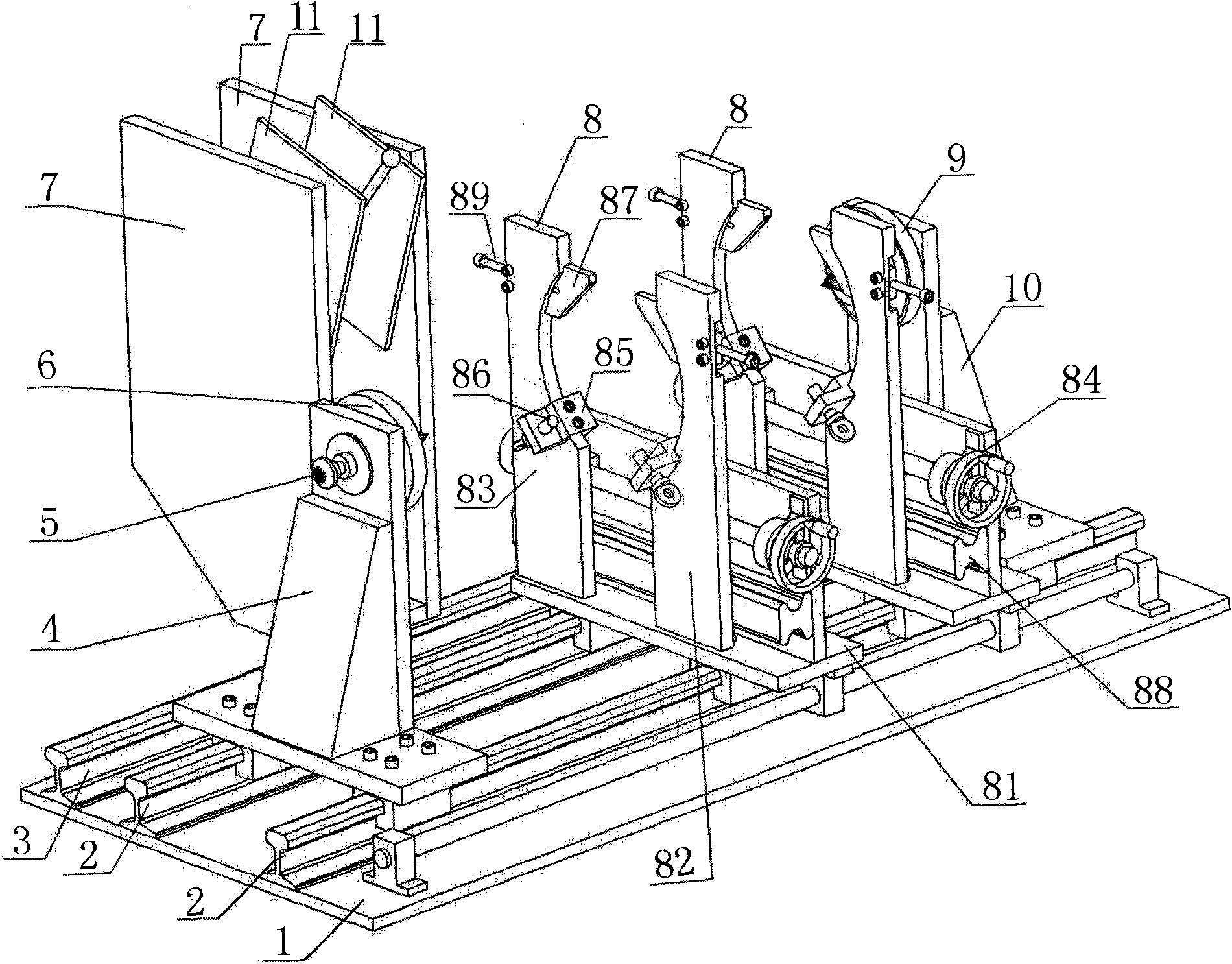
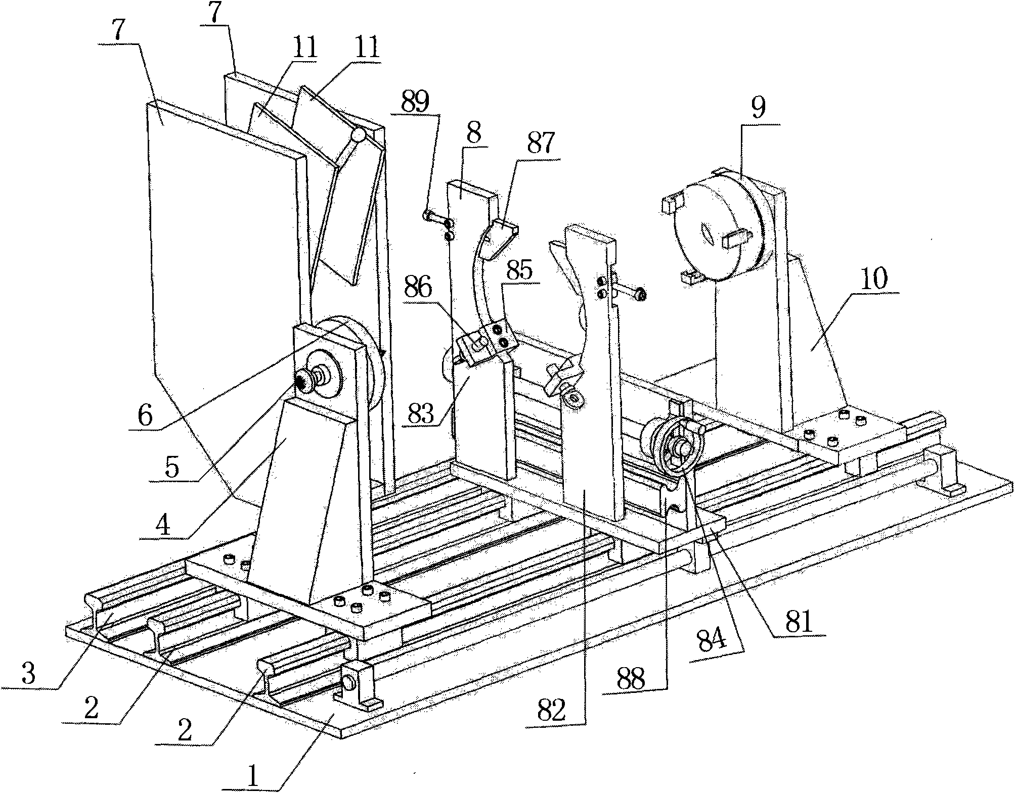
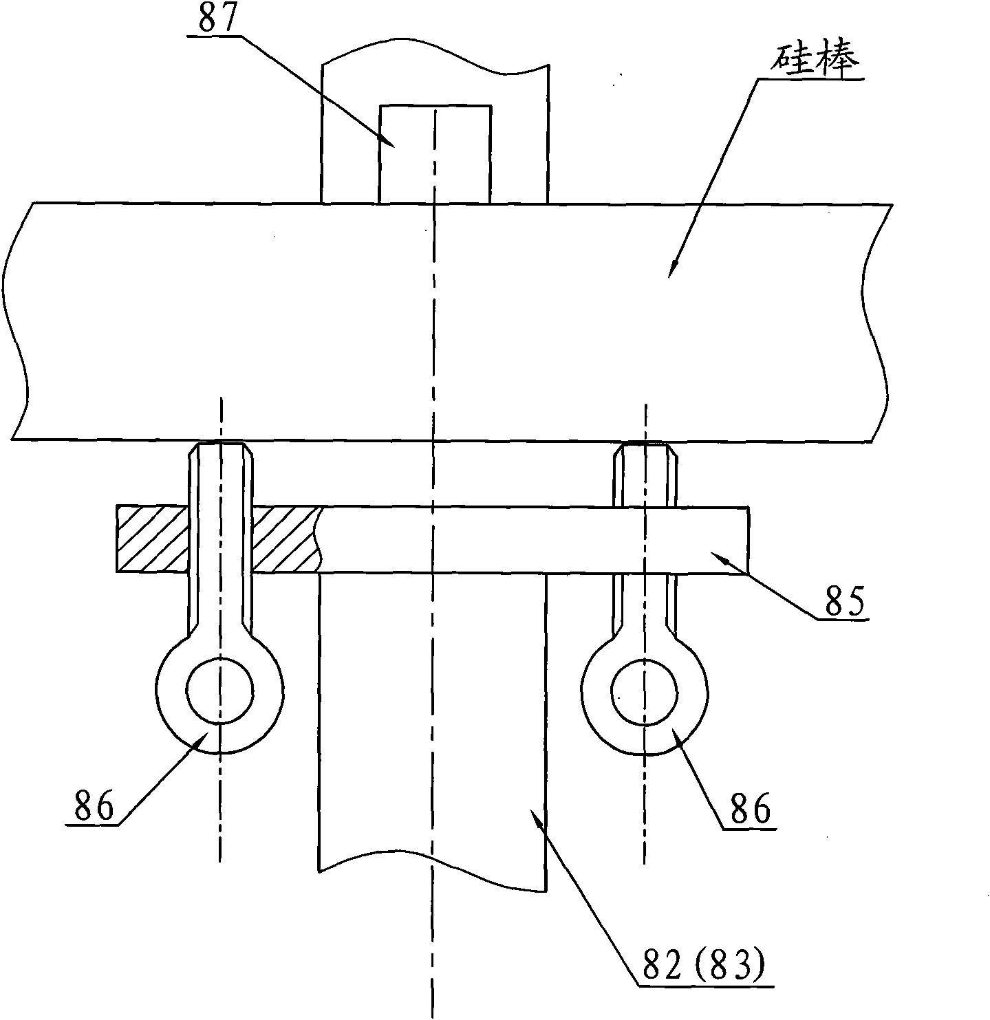
[0014] A single clamping frame silicon rod gluing machine, as attached figure 2 , image 3 As shown, it consists of a base 1, a silicon rod support guide rail 2, a heating device guide rail 3, a left slide seat 4, an adjusting screw 5, a circle center calibration disc 6, a heating device 7, a silicon rod clamping mechanism 8, a three-jaw chuck 9, The right slide 10 is composed of a crystal holder 11, the silicon rod support rail 2 and the heating device guide rail 3 are fixed on the base 1 in parallel, the left slide 4 is installed on the silicon rod support guide 2, and is located on the left side of the base 1, the center of the circle The calibration disc 6 is installed on the left sliding seat 4 through the adjusting screw 5; the right sliding seat 10 is also installed on the silicon rod support guide rail 2, and is located on the right side of the base 1, and the three-jaw chuck 9 is installed on the right sliding seat 10, And the center of the three-jaw chuck 9 is coll...
PUM
 Abstract
Description
Claims
Application Information