Car or train running system and housing body thereof

A technology for trains and covers, applied in the field of transportation, can solve problems such as the difficulty of increasing the speed of high-speed trains, and achieve the effect of reducing energy consumption and increasing natural speed

Active Publication Date: 2011-02-16
朱晓义
View PDF7 Cites 14 Cited by
  • Summary
  • Abstract
  • Description
  • Claims
  • Application Information

AI Technical Summary

Problems solved by technology

[0002] When cars and trains run fast, they consume more energy to overcome fluid resistance. This energy consumption has always been the largest energy consumption of cars or trains. In addition, due to fluid resistance, it is difficult to increase the speed of high-speed trains.

Method used


Image

  • Car or train running system and housing body thereof
  • Car or train running system and housing body thereof
  • Car or train running system and housing body thereof

Examples


Embodiment 1

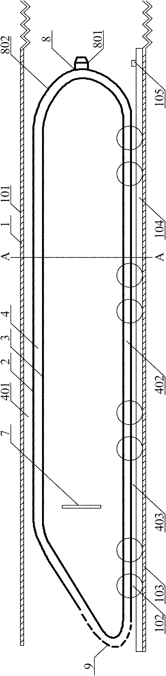
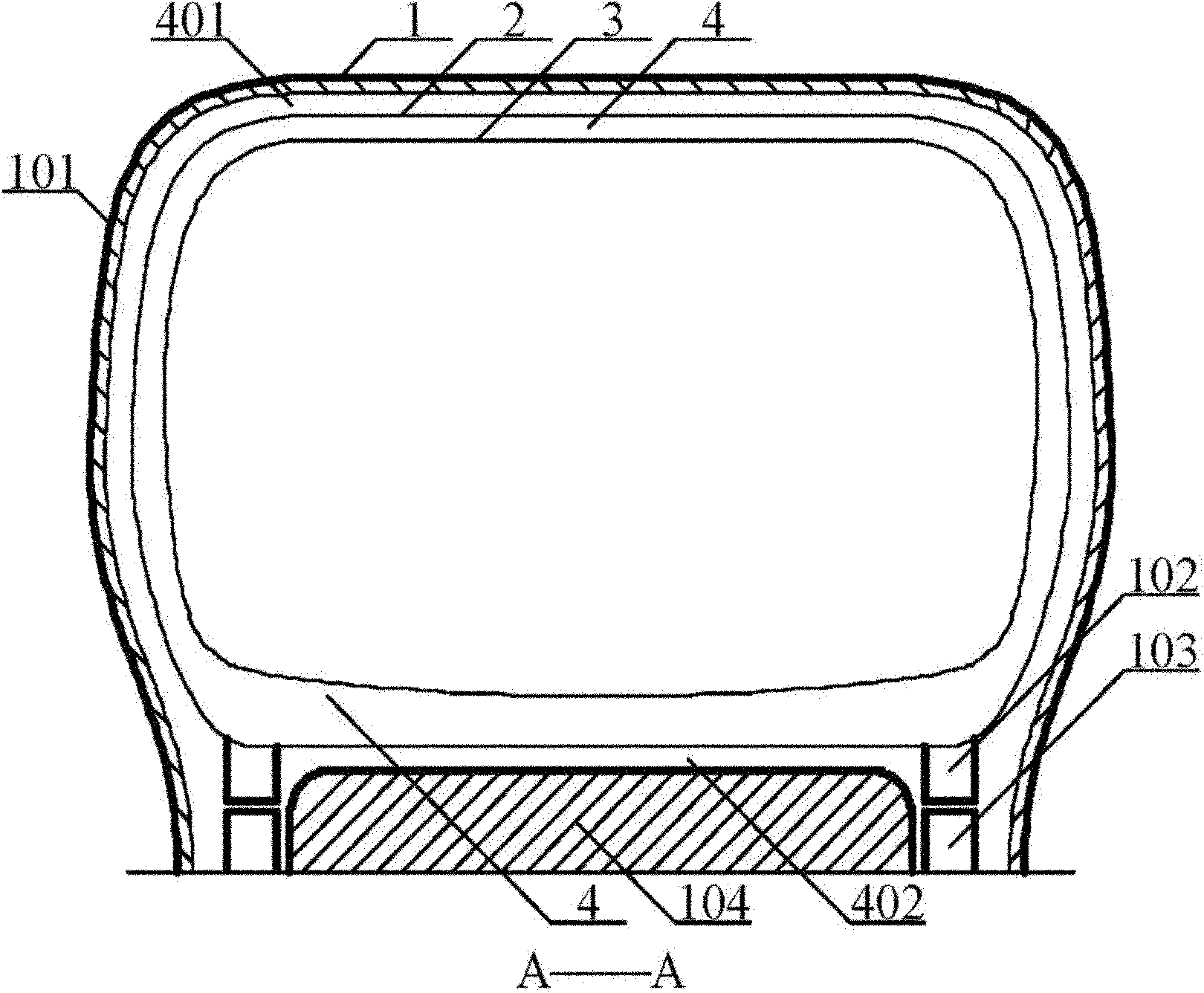
[0055] Example 1, such as Figure 1-2 As shown, the train is closed to run in the cover body 1. The two sides and the top of the cover body shell are covered with solar cells, such as solar energy collection panels 101 (or films), which are converted into electric energy and stored in a plurality of accumulators 105. Thousands of kilometers long The solar collection plate 101 on the cover shell forms a very large-scale solar power plant, which generates enough power to drive the train, and can also output the remaining electric energy. The outside of the window corresponding to the train on both sides of the cover body 1 can be a transparent material, a sufficiently large front inlet 9 at the front of the train with the same width as the housing, and multiple lateral pressure inlets 7 around the surroundings and the annular interior air surrounding the train. Passage 4 communicates with the middle export port 8 at the rear. The guide body 802 is semicircular around the export ...

Embodiment 2

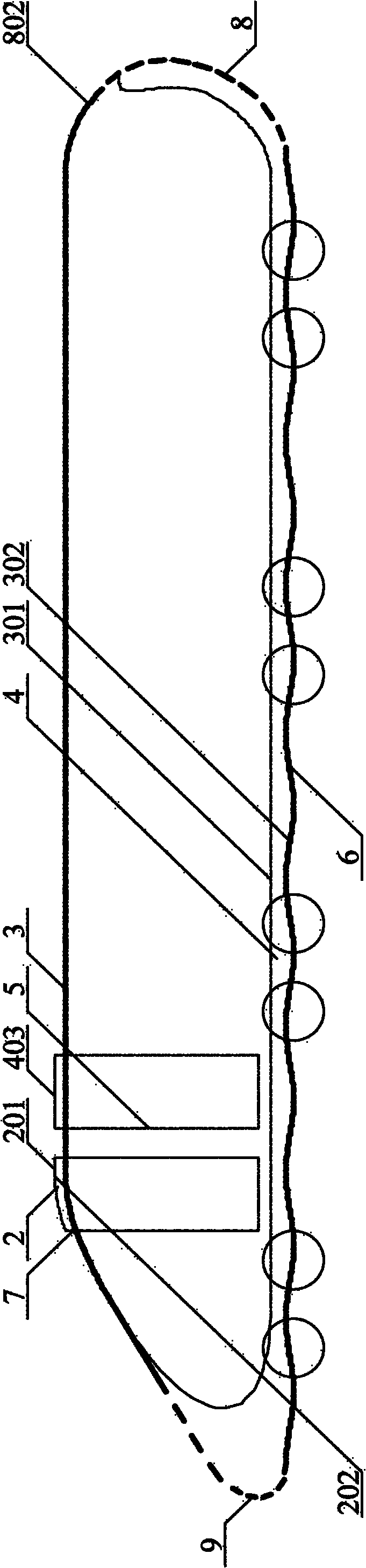
[0059] Example 2, such as image 3 As shown, the difference from Example 1 is that the image 3 Put it in the cover body 1, remove the filling block 104 (not shown), the front end is provided with the front end inlet 9 about the same width as the housing, and the bottom fluid channel 4 communicates with the rear end outlet 8 about the same width of the housing. The spoiler 2 evenly distributed on both sides and the upper part forms a shell, the outer surface 201 of the spoiler 2 is an arc surface, and the inner surface 202 is a plane, the front of each spoiler 2 is a pressure inlet 7, and the rear is a pressure outlet 5. There is a fluid layer 403 between the inner surface 202 of the spoiler and the inner shell 3, and a concave-convex spoiler surface 6 at the bottom, so that the path of the fluid passing through here is larger than its upper part.

[0060] When the train is running fast, a large amount of fluid at the front end is discharged from the large enough front inlet ...

Embodiment 3

[0066] Embodiment 3 is different from the above, Figure 5 Putting the maglev train into the cover body 1 (not shown), the paths of fluids on the inner and outer surfaces of multiple spoilers 2 around the train are different to generate a pressure difference, thereby forming a pressure difference transfer zone around the whole train. The cover body better transfers the high-pressure area around the train shell to the outer low-pressure area, so that the fluid resistance is greatly reduced. The maglev train has no friction between the wheels and the rails, and the pressure difference transfer area around the train makes the surrounding Fluid resistance is greatly reduced, so the movement speed is greatly improved.

[0067] This embodiment is not in the cover body, which can also increase the speed and save energy.


PUM


Abstract

The invention discloses a car or train running system and a housing body thereof. The housing body is fixed above a railway or a road and comprises a top, two side edges connected with the top, solar cells and an energy storage device, wherein, the distance between the top of the housing body and the railway or the road is more than the height of a train or a car; the bottom edges of the two sideedges of the housing body are fixed at two sides of the railway or the road; the solar cells are arranged on the top and the two side edges of the housing body or the whole housing body and are connected with the energy storage device; and the energy storage device supplies electric energy to the traveling car or train in the housing body. By adopting the system and the housing body of the invention, the car or the train can run at a high speed with lower energy consumption.

Description

technical field [0001] The invention relates to the technical field of transportation, in particular to an automobile or train running system and a cover body thereof. Background technique [0002] When cars and trains run fast, they consume more energy to overcome fluid resistance, which has always been the largest energy consumption of cars or trains; in addition, due to fluid resistance, it is difficult to increase the speed of high-speed trains. [0003] In the patent application named "Train" with the application number 200910109252.7 and the patent application named "Automobile or Train" with the application number 201010266825.x, the applicant proposes that the inlet and outlet are communicated with the fluid channel and the pressure difference transfer area. Reduce fluid resistance. [0004] The applicant also noticed that a Chinese utility model patent No. 200920148447.8 was published on February 24, 2010, which discloses a wind, snow and sand protection cover for ...

Claims


Application Information

Patent Timeline
Patent Type & Authority Applications(China)
IPC IPC(8): B62D37/02B61D17/00B61B13/10B60L9/00
CPCY02T30/40Y02B10/30Y02T30/00
Inventor 朱晓义
Owner 朱晓义
Why Eureka
Try Eureka