Hydraulic vane pump

A vane pump, hydraulic technology, applied in the field of hydraulic pumps, can solve the problems of stator wear performance, insufficient effective pressure, unreliable work, etc., to achieve good working life, reduce system configuration costs, and avoid wear and tear.

Inactive Publication Date: 2011-02-16
ZHEJIANG TAIZHOU XIANDING HYDRAULIC CO LTD
View PDF5 Cites 2 Cited by
  • Summary
  • Abstract
  • Description
  • Claims
  • Application Information

AI Technical Summary

Problems solved by technology

Due to the limitations of the structural design of the existing mother-in-law vane pumps and pin-type vane pumps, it is impossible to ensure good control of the pressure on the inner surface of the stator by the vanes in the whole process of the pump from low pressure to high pressure under the condition of higher working pressure, resulting in Wear at higher operating pressures
A sub-vane is installed in each vane of the existing mother-in-command vane pump, and a pin is installed in each rotor slot of the pin-type vane pump. The pressure is reduced to the pressure formed on the sub-blade or pin corresponding to the fluid stress area, but it is necessary to take into account the low-pressure stage of the pump to ensure the effective pressure of the blade on the inner surface of the stator and the maximum pressure of the blade to the inner surface of the stator in the high-pressure stage. It is feasible within a certain range. If the working pressure of the pump is further increased, it will cause unreliable work, stator wear and work performance deterioration. At this time, if the effective pressure in the low-pressure stage is ensured, the fluid film layer will penetrate in the high-pressure stage. If the maximum The pressure will cause insufficient effective pressure in the low pressure stage

Method used


Image

  • Hydraulic vane pump
  • Hydraulic vane pump
  • Hydraulic vane pump

Examples


Embodiment Construction

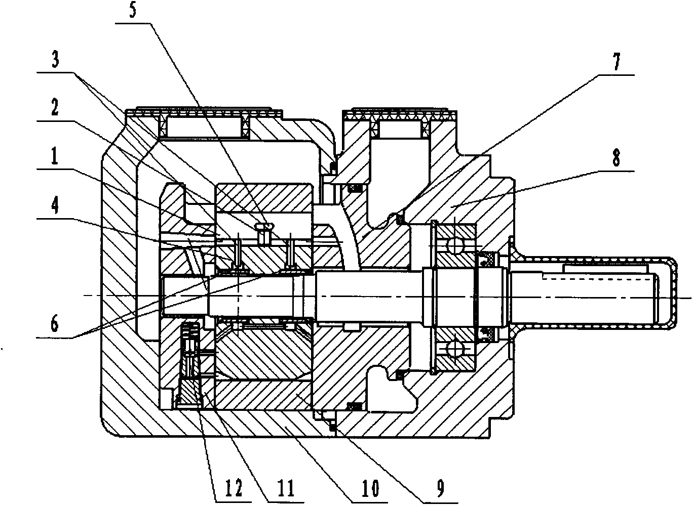
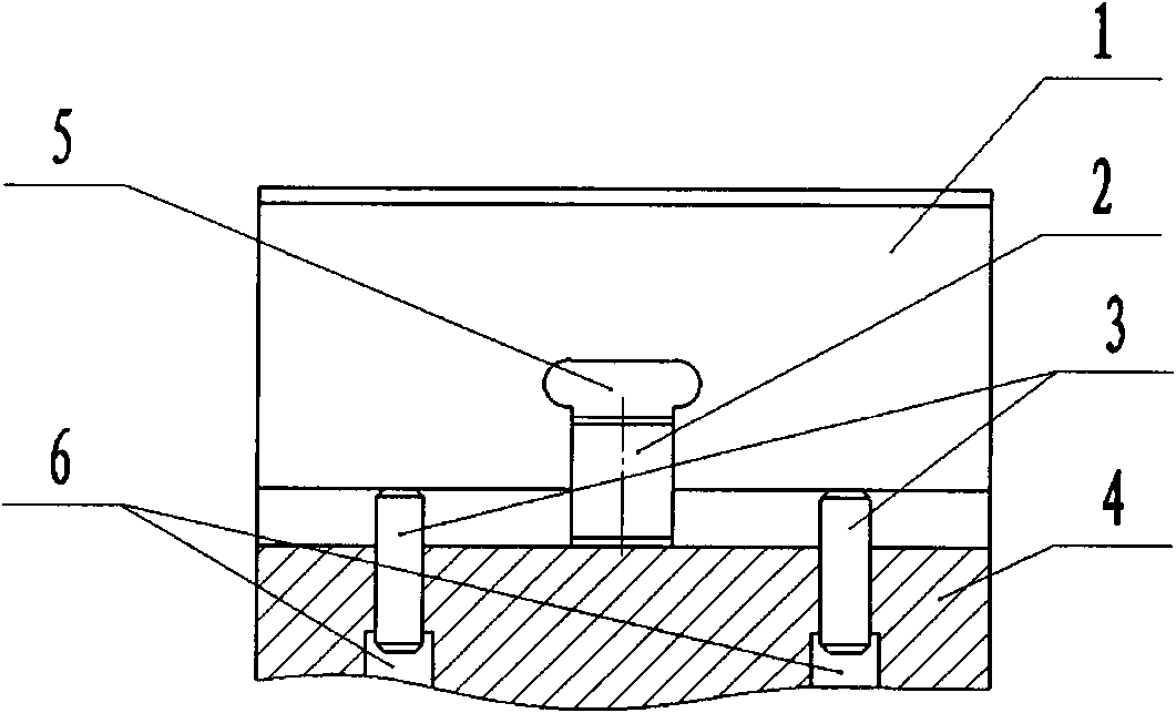
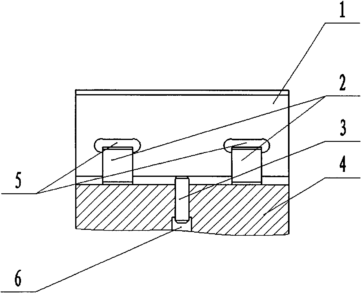
[0031]The hydraulic vane pump of the present invention includes a pump body (including the left and right pump bodies) with a fluid inlet and outlet and an inner cavity, and a rotatable rotor with a plurality of rotor grooves distributed radially (including the integral rotor and the split rotor composed of two half rotors). , the stator placed outside the rotor, the side plates (including the left and right side plates) located at both ends of the rotor stator, the protruding and retractable blades located in each rotor slot, and one or more sub-blades installed at the lower part of each blade 1. One or more pins installed at the bottom of each rotor slot; two protruding adjacent blades form a pumping space with the inner surface of the stator, the outer circle of the rotor, and the two side plates. When the rotor rotates and the blades protrude When the volume of the pumping space expands and shrinks alternately to produce suction and discharge for the fluid, one or more volu...


PUM


Abstract

The invention discloses a hydraulic vane pump. In the hydraulic vane pump, one or more of sub-vanes are arranged on the lower part of each vane; the bottom of each rotor slot is provided with one or more of pins while the corresponding sub-vane cavities and the pin cavities are formed respectively; auxiliary valves are adopted to control the on / off switching of the pressure fluid passages of the sub-vane cavities or the pin cavities so as to provide pressure fluid for all the cavities or partial cavities selectively, change the total stressed area of the pressure fluid cavities on each vane in the volume-expanding region of the pump. Therefore the pressure on the inner surface of the stator can be controlled reasonably in different pressure stages, the wear failure of the stator can be well avoided, the working pressure of the hydraulic vane pump can be greatly increased, the demand of the high-pressure hydraulic system on the vane pump can be satisfied; the hydraulic vane pump can also have higher working pressure under fluid conditions such as low viscosity medium and high water-based medium; and the manufacturing technology and equipment of the vane pump of the invention are basically the same of that of the existing vane pump, and the manufacturability is better.

Description

technical field [0001] The invention relates to a hydraulic pump, in particular to an improved hydraulic vane pump. Background technique [0002] The wear failure of the inner surface of the stator of the hydraulic vane pump is the main factor hindering the further increase of the pump pressure. The existing mother-in-law vane pump and pin-type vane pump are the main structural forms used in the high-pressure vane pump at present, and the application is relatively common. Corresponding measures are taken to reduce the pressure of the vane on the stator, so that the vane pump has a certain working pressure. , to meet the needs of some host hydraulic systems. The vane pressure on the inner surface of the stator in the fluid inflow section (that is, the low-pressure section) is relatively high, and it is easy to fail first. The maximum pressure should be controlled to ensure that the vane does not penetrate the protective fluid film layer on the inner surface of the stator dur...

Claims


Application Information

Patent Timeline
Patent Type & Authority Applications(China)
IPC IPC(8): F04C2/34
Inventor 胡凯王新彪
Owner ZHEJIANG TAIZHOU XIANDING HYDRAULIC CO LTD
Why Eureka
Try Eureka