Ceramic plate detection equipment and detection method

A technology for testing equipment and ceramic plates, which is applied in the direction of measuring devices, instruments, and material analysis through optical means. It can solve the problems of straight laser lines, missing edges, missing corners, and drum edges, etc., to achieve efficient and accurate detection. , The effect of simple detection process

Inactive Publication Date: 2011-02-16
HANGZHOU SANSU TECH
View PDF4 Cites 24 Cited by
  • Summary
  • Abstract
  • Description
  • Claims
  • Application Information

AI Technical Summary

Problems solved by technology

The purpose of this is: since the laser emitter can emit laser light on the edge of the tested ceramic plate, if the ceramic plate is flat, the laser line will be str

Method used


Image

  • Ceramic plate detection equipment and detection method
  • Ceramic plate detection equipment and detection method
  • Ceramic plate detection equipment and detection method

Examples


Embodiment 1

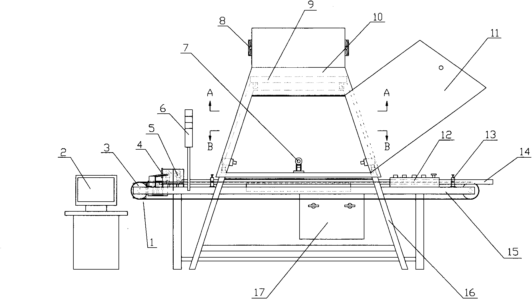
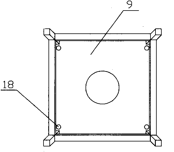
[0011] Embodiment 1: with reference to attached Figure 1~3 . A kind of ceramic plate detection equipment, it comprises conveying mechanism 1 and support 16, described is provided with conveying mechanism 1 and is positioned at support 16, is positioned at the four sides of support 16 above conveying mechanism 1 and is respectively provided with linear laser emitter 7 and angle is adjustable, The linear laser line shot obliquely from top to bottom by the linear laser emitter 7 forms a rectangular linear laser frame on the conveying surface of the conveying mechanism; The signal output end of the high-resolution industrial camera 18 is connected with the computer 2 signal input end.

[0012] The support 16 is a trapezoid with a small upper part and a larger lower part, and the area formed by the intersection of the interior of the support 16 with the conveying mechanism 1 is the detection area. Four crossbars 25 are arranged at the detection position of the trapezoid, and the...

Embodiment 2

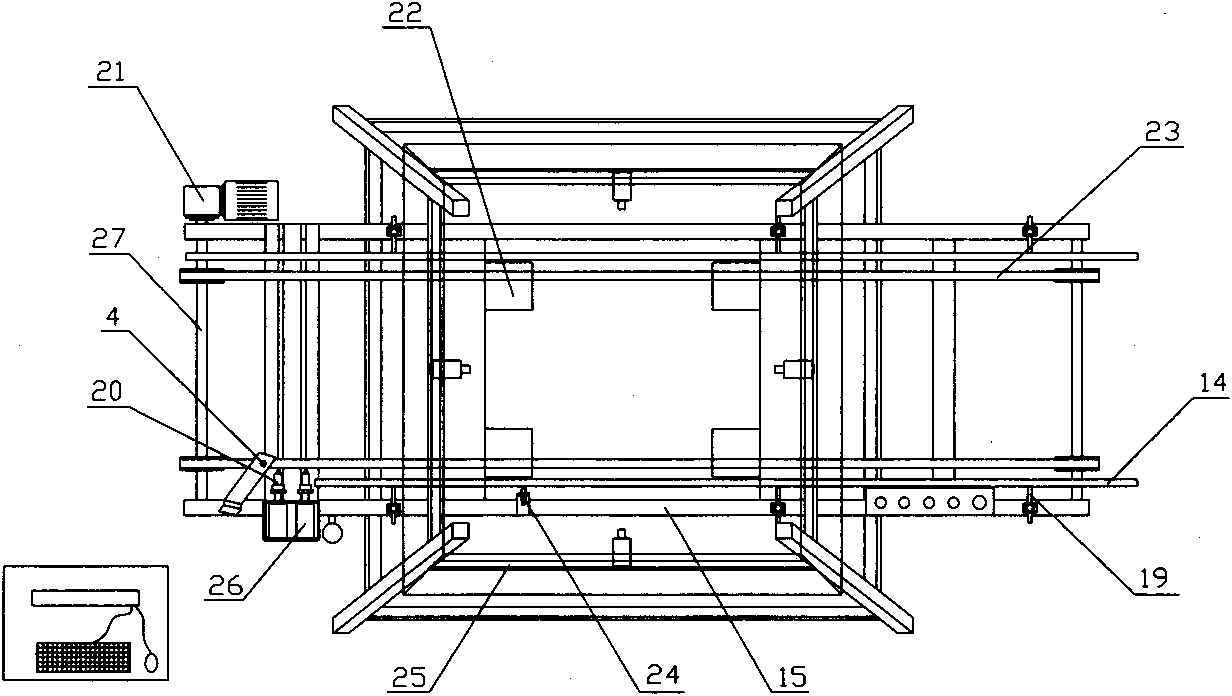
[0019] Embodiment 2: On the basis of embodiment 1, a kind of ceramic plate detection method, (1) the optical detection probe 24 that is positioned at one side of assembly line, after detecting the arrival of ceramic plate, stop conveying by controller instruction conveying mechanism, four The area occupied by the backlight board 22 is greater than the area of ​​the detected ceramic board, so the light projected by the four backlight boards 22 positioned directly below the ceramic board irradiates the edge of the ceramic board to show the outline of the ceramic board. Four ultra-high-resolution industrial cameras 18 immediately take pictures of the ceramic plate against the flicker-free plane backlight and input it into the computer to save the picture. After the computer software rapid graphic image analysis and calculation processing, the length of the four sides of the ceramic plate and its composition are obtained. (2) the linear laser lines emitted by the four linear laser ...


PUM


Abstract

The invention relates ceramic plate detection equipment and detection method thereof, which can rapidly and accurately detect the technical parameters of a ceramic plate to be detected and can mark the ceramic plate according to the detection result. The ceramic plate detection equipment comprises a conveying mechanism and a support, wherein the conveying mechanism is positioned in the support; four sides of the support, which are arranged above the conveying mechanism are respectively provided with a linear laser transmitter with adjustable angle, the linear laser lines obliquely transmitted by the linear laser transmitters from top to down form a rectangular linear laser frame on the conveying surface of the conveying mechanism; the four angles of the upper part of the support and the conveying mechanism are respectively provided with an ultra high-resolution industrial camera the signal output end of which is connected with the signal input end of a computer. The invention has the following advantages: 1, the diction process is simple and fast, the detection is accurate and the detection efficiency is high; and 2, the structure is simple, the equipment has the function of automatically identifying marks so as to effectively prevent artificial sorting errors.

Description

technical field [0001] The invention relates to a ceramic plate detection device and a detection method capable of quickly and accurately detecting the technical parameters of the ceramic plate to be inspected and marking the ceramic plate according to the detection result, belonging to the technical field of ceramic plate detection equipment manufacturing. Background technique [0002] CN101169452A, titled "ceramic brick quality detection method and equipment". It includes a conveying device, a data acquisition device, a data transmission device, a pause device and a data processing device arranged on the frame. The pause device consists of a front brick positioning mechanism, a rear brick positioning mechanism, a centering mechanism, a brick jacking mechanism, an upper It is composed of a position mechanism and a photoelectric switch bracket, and the pause device is a control switch controlled by a sensor, manually controlled or programmed to control the operation of the c...

Claims


Application Information

Patent Timeline
IPC IPC(8): G01N21/892G01B11/16G01B11/24
Inventor 彭崇荣
Owner HANGZHOU SANSU TECH
Why Eureka
Try Eureka