
Optical detection method for parallelism of planar array CCD target surface and installation locating surface
An optical detection, installation and positioning technology, applied in the direction of using optical devices, measuring devices, mechanical gap measurement, etc., can solve the problems of difficult optical system focal depth requirements, poor parallelism of CCD target surface, affecting the quality of CCD imaging, etc. Improved image quality, easy operation, and the effect of reliable measurement methods
- Summary
- Abstract
- Description
- Claims
- Application Information
AI Technical Summary
Problems solved by technology
Method used
Image

Examples
specific Embodiment approach 1
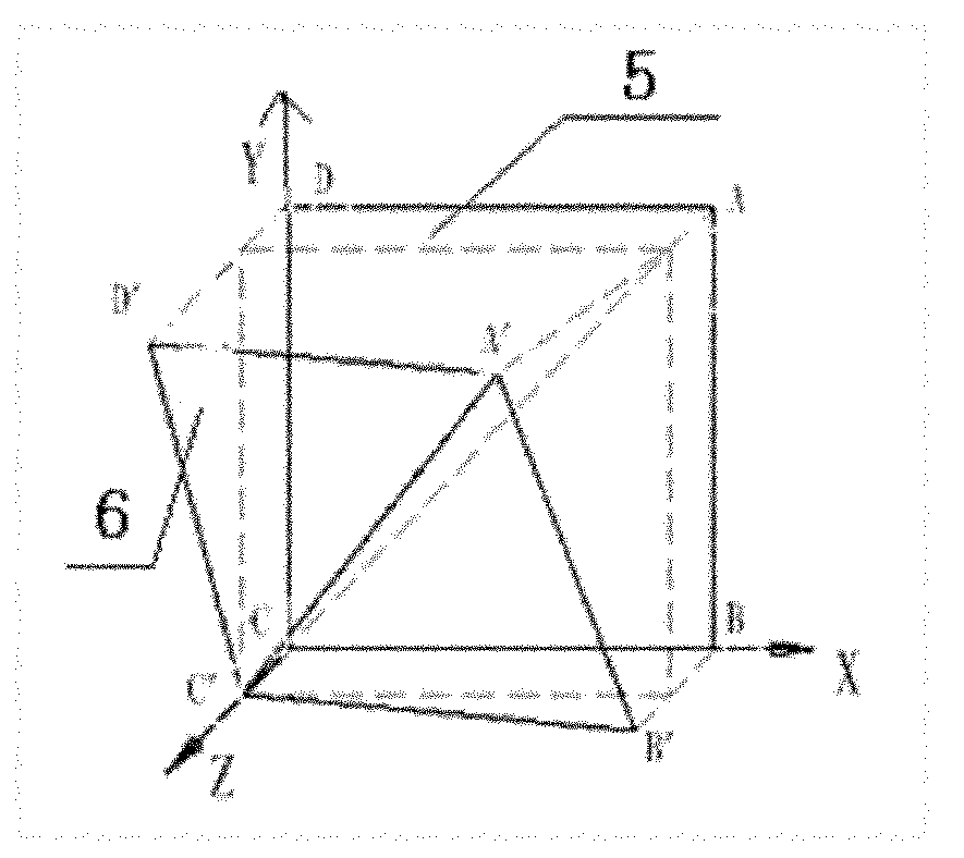
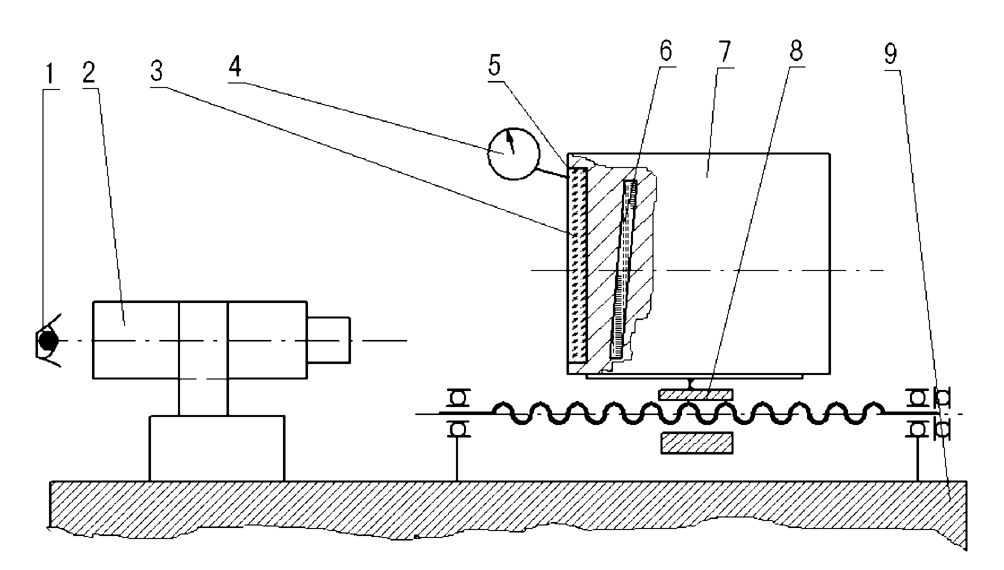
[0016] Specific implementation mode 1. Combination figure 1 and figure 2 Illustrate this embodiment, a kind of optical detection method of the parallelism between the target surface 6 of the area array CCD and the installation positioning surface, the method is completed by the following steps:
[0017] Step 1, using a high-precision linear displacement platform 8 to move the CCD target surface 6 and the mechanical installation surface 5 to the focal plane of the tool microscope 2 respectively;
[0018] Step 2, using the dial indicator 4 to measure the moving distance of the high-precision linear displacement platform 8, and using the moving distance of the high-precision linear displacement platform 8 as the distance between the CCD target surface 6 and the mechanical installation surface 5;
[0019] Step 3: Use any right-angled vertex of the CCD target surface 6 as the origin of the Cartesian coordinate system, and the corresponding two right-angled sides as the X-axis and...
specific Embodiment approach 2
[0022] Specific embodiment two, combine figure 2 Describe this embodiment, this embodiment is the specific example of the optical detection method of the parallelism of a kind of area array CCD target surface 6 described in the specific embodiment 1 and the installation positioning surface:
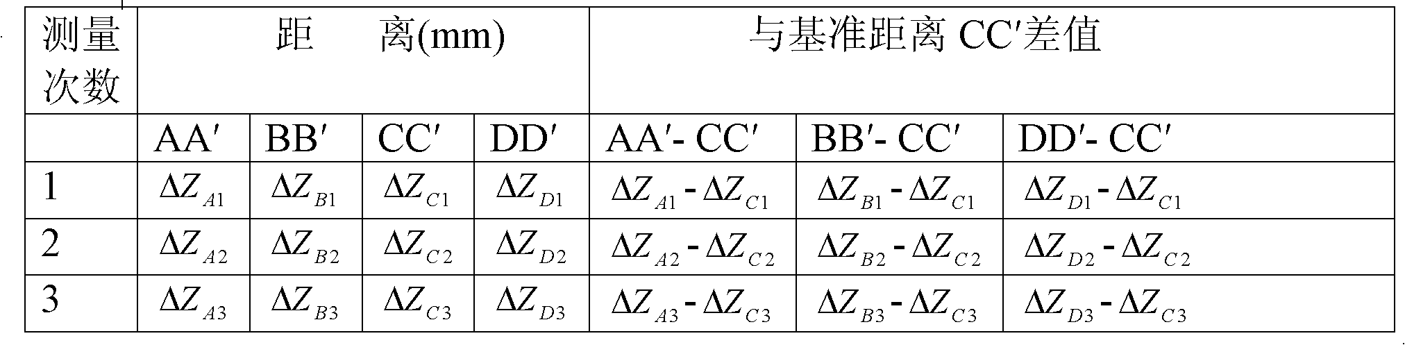
[0023] The measuring tool of the present embodiment is: tool microscope 2, dial indicator 4, high-precision linear displacement platform 8; the displacement resolution of the high-precision linear displacement platform 8 is 0.005; the measuring tool is placed on the marble platform 9, A CCD protective glass 3 is arranged in front of the rectangular area array CCD target surface 6, and a non-contact optical measurement method is adopted to observe the value read by the tool microscope 2 through the human eye 1 and calculate the distance between the CCD target surface 6 and the mechanical installation surface 5 on the X axis, The angle between the Y axis and the diagonal direction, and the...
PUM
 Abstract
Description
Claims
Application Information