
Reverse recovery protection test method of thyristor

A technology of protection test and thyristor, which is applied in the field of power system devices, can solve problems such as difficult impact voltage value, inability to realize precise control, difficult control of time adjustment method, etc., achieve strong automatic control ability, high repeatability, and reduce human operation Effect

Active Publication Date: 2013-12-18
CHINA ELECTRIC POWER RES INST +1
View PDF1 Cites 0 Cited by
  • Summary
  • Abstract
  • Description
  • Claims
  • Application Information

AI Technical Summary

Problems solved by technology

In the patent CN200710178248.7 DC converter valve recovery period instantaneous forward voltage test method, it is mentioned that the impulse voltage is applied to the test valve during the shut-off process of the DC converter valve thyristor through a synthetic experimental device. The recovery period protection test method is to test the DC converter valve module. Due to the high amplitude of the impulse voltage in this test, it is difficult to generate the impulse voltage value of the test for a single thyristor. The time adjustment of the positive impact during the recovery period The method is more difficult to control and cannot achieve the purpose of precise control

Method used


Image

  • Reverse recovery protection test method of thyristor
  • Reverse recovery protection test method of thyristor
  • Reverse recovery protection test method of thyristor

Examples


Embodiment Construction

[0016] In order to describe in detail the test method of the thyristor recovery period protection test designed in the present invention, it will be described in conjunction with examples below.

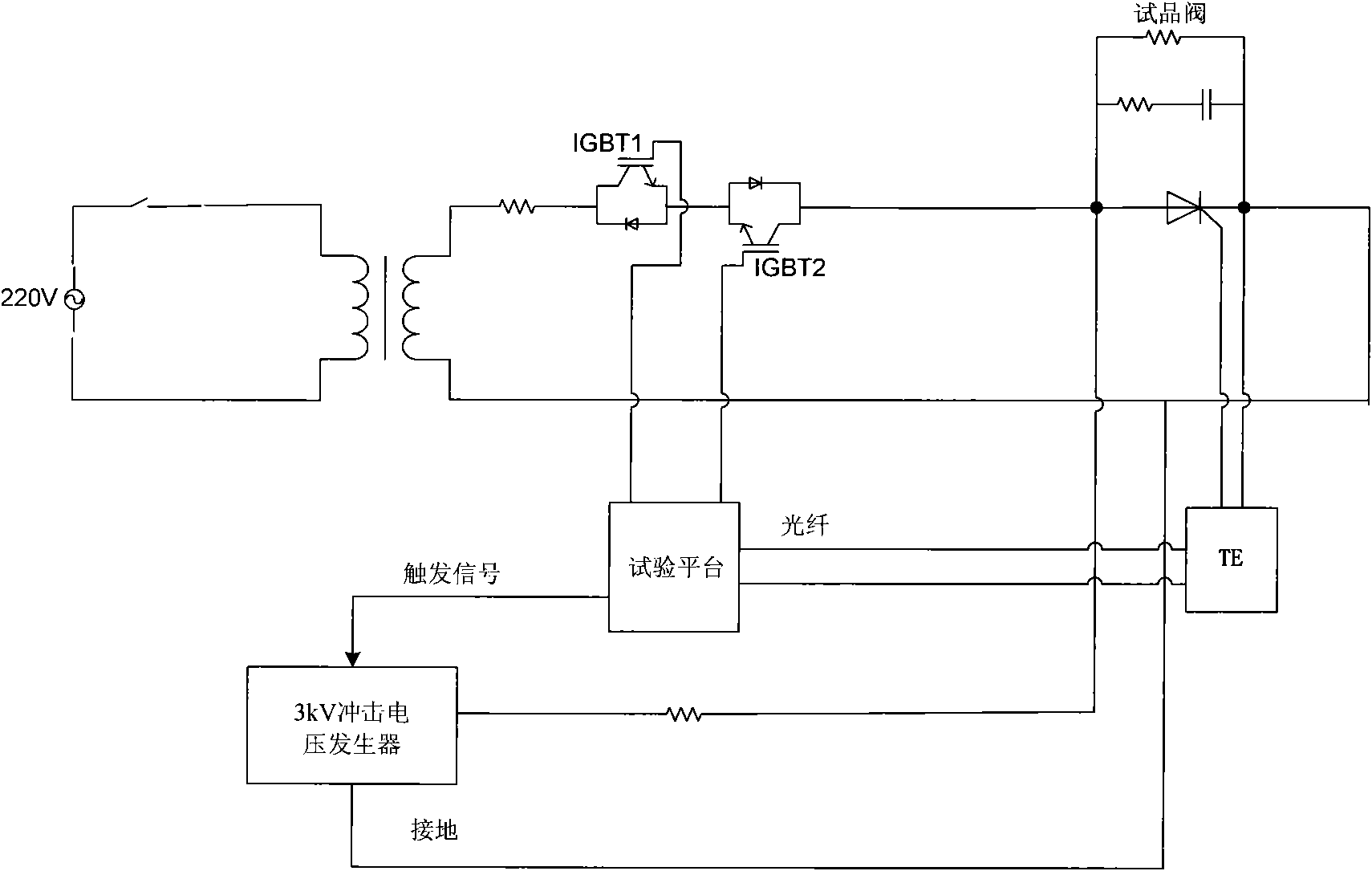
[0017] Reference attached figure 1 . The thyristor recovery period protection test circuit is composed of 220V AC source, isolation switch, isolation transformer, current limiting resistor, IGBT, thyristor level test product, 3kV impulse voltage generator and test platform. The output terminal of the 220V AC source is connected with the isolation switch, and the isolation switch is connected with the isolation transformer. The output terminal of the isolation transformer is connected with the current limiting resistor, and the current limiting resistor is connected with the IGBT. The output end of the IGBT is connected to the thyristor-level test object, and the high-voltage end of the impulse voltage generator is connected to the thyristor-level test object. The impulse voltage g...


PUM


Abstract

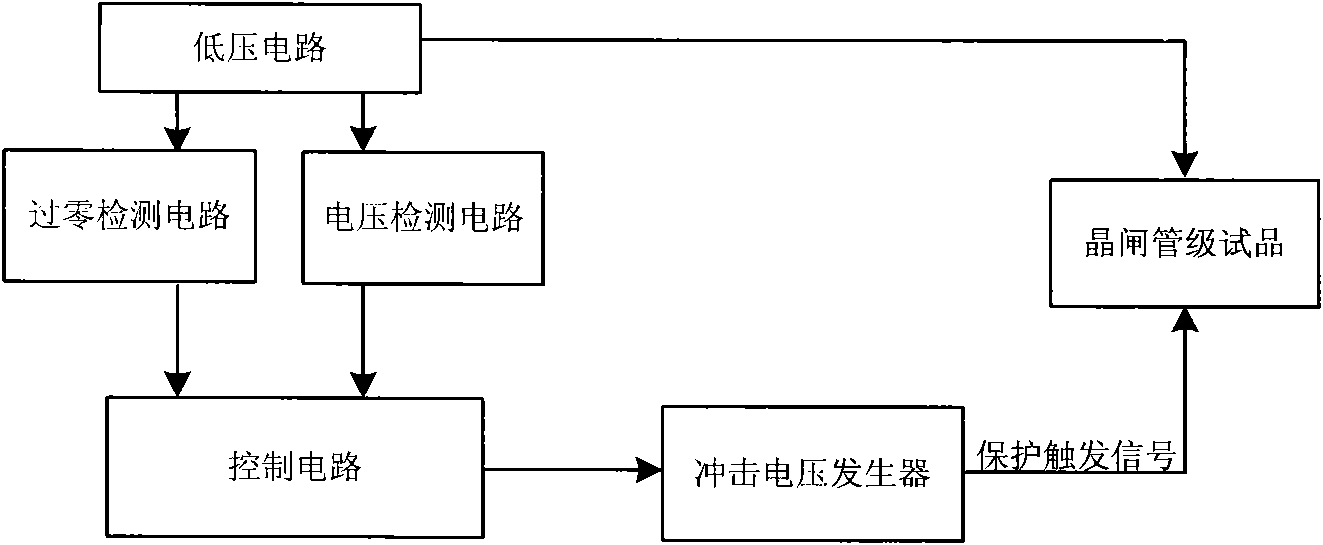
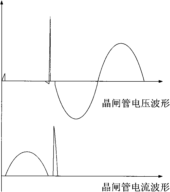
The invention provides a novel reverse recovery protection test method of a thyristor. Because the forward voltage endurance capacity of the thyristor during the recovery period is lower, if the overvoltage occurs, the thyristor can be possibly damaged, and thyristor electronic equipment (TE) generally has a thyristor recovery period protection function in a direct current transmission project. A test circuit disclosed in the method comprises a low-voltage loop and an impact voltage generator, wherein the low-voltage loop provides a normal working voltage for the thyristor, and the impact voltage generator generates an impact waveform applied to a thyristor grade. During the test, the on / off of an IGBT (Insulated Gate Bipolar Translator) is controlled through a test platform so as to isolate the low-voltage loop and the impact loop; the control time sequence of the system ensures that the thyristor sends a trigger ignition pulse to the impact voltage generator when in a recovery period to make the impact voltage applied to the thyristor grade. When an impact voltage value is more than the recovery period voltage protection level of the TE, the thyristor is protectively triggered, thus the thyristor is prevented from being damaged due to the overhigh forward voltage. The test method changes the traditional method of depending on the measurement and the regulation of a power frequency electrical degree, reduces the manual operations and improves the reliability.

Description

technical field [0001] The invention relates to the field of power system devices, in particular to a novel thyristor reverse recovery protection test method. Background technique [0002] During the turn-off process of the thyristor, the current drops from the rated value to zero before it has the ability to withstand the reverse voltage. Due to the existence of the junction capacitance of the thyristor, a certain reverse recovery charge is required to make the current flow in the reverse direction after crossing zero. This process is called the reverse recovery period. During normal operation, the thyristor is subjected to power frequency AC voltage during the reverse recovery period, and the dv / dt is within the allowable range. If there is AC network voltage disturbance, commutation failure, lightning shock, etc. during this period, the thyristor may be doubled. The dv / dt of the end exceeds the standard. Therefore, protection for the reverse recovery period must be appl...

Claims


Application Information

Patent Timeline
Patent Type & Authority Patents(China)
IPC IPC(8): G01R31/26
Inventor 汤广福陈龙龙王华锋
Owner CHINA ELECTRIC POWER RES INST
Learn More