Microscope automatic control platform based on portable bypass structure

A technology for microscopes and consoles, applied in microscopes, optics, instruments, etc., can solve the problems of complicated operation and use of microscopes, increased eye fatigue, and reduced observation accuracy, and achieves solutions to the problem of knob linkage, simple control, and low cost. Effect

Inactive Publication Date: 2012-11-07
JIANGSU UNIV
View PDF0 Cites 1 Cited by
  • Summary
  • Abstract
  • Description
  • Claims
  • Application Information

AI Technical Summary

Problems solved by technology

[0002] At present, microscopes have been widely used in various fields such as education, biology, and medical treatment. However, the operation of most microscopes is cumbersome. If there are many samples to be observed, the observation time will be long, and the degree of eye fatigue will increase, which will not only damage the body, but also greatly reduce the accuracy of observation.

Method used


Image

  • Microscope automatic control platform based on portable bypass structure
  • Microscope automatic control platform based on portable bypass structure
  • Microscope automatic control platform based on portable bypass structure

Examples


Embodiment Construction

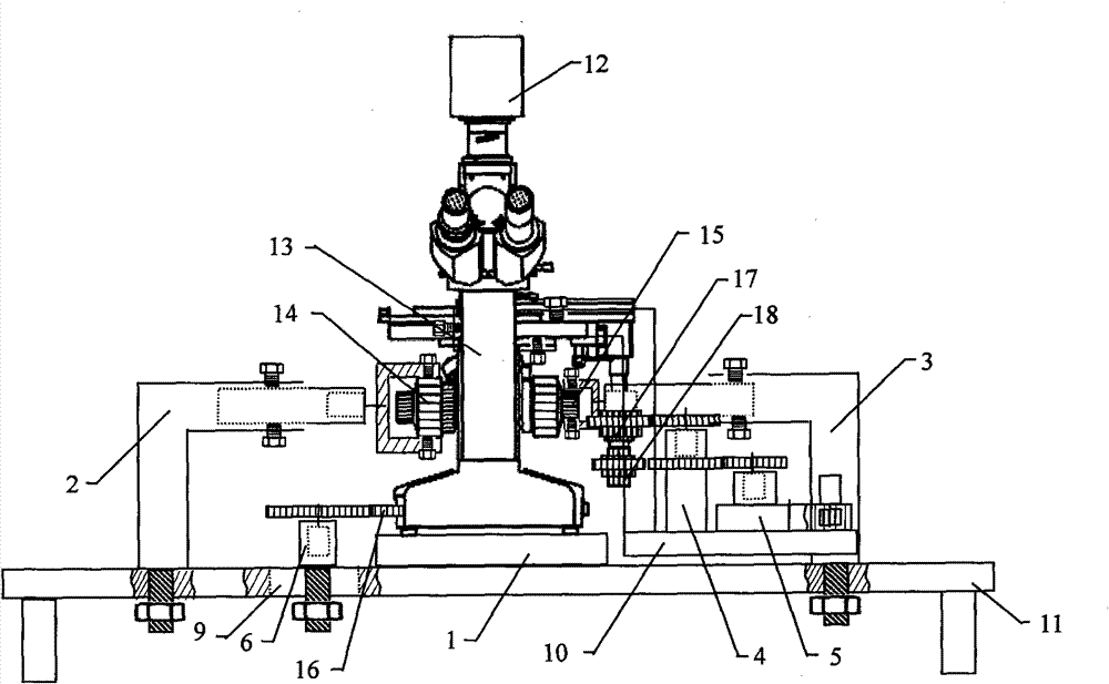
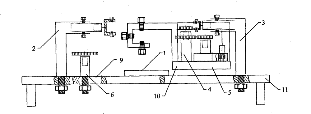
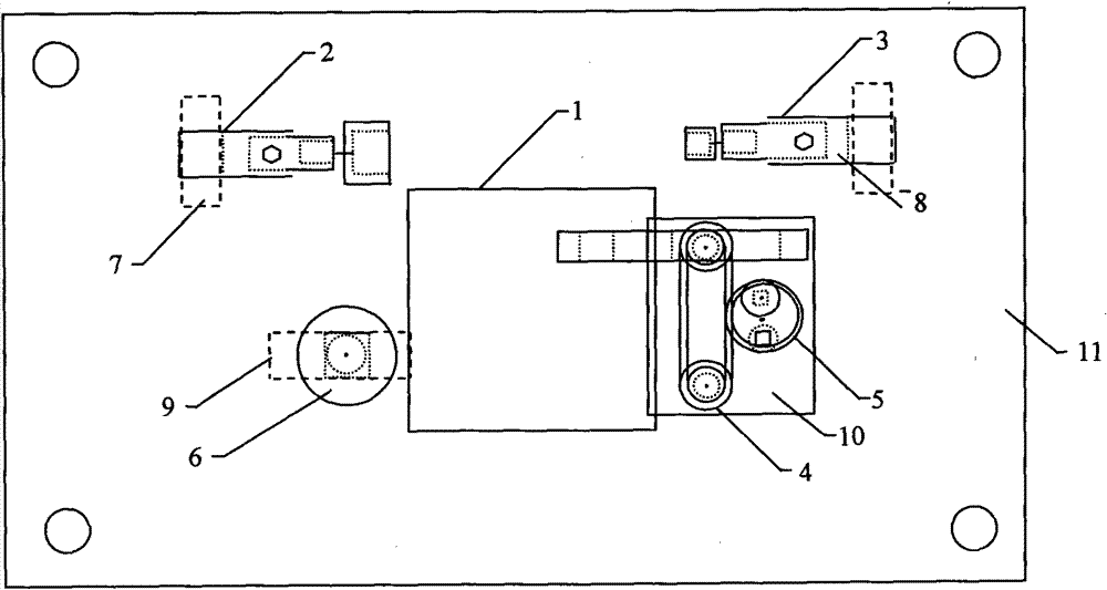
[0029] see Figure 1-3 , the lowermost part of the present invention is the control platform 11, and the central placement platform 1, the coarse focus control mechanism 2, the fine focus control mechanism 3, the follow-up lifting platform 10, the light source control mechanism 6, and the microscope carrier are respectively installed on the control platform 11. The X-direction control mechanism 4 and the Y-direction control mechanism 5 of the object stage. The microscope 13 is placed on the central stage 1. The stage focal length adjustment knobs 14 and 15 of the microscope 13 are respectively located on both sides of the stage, and the X-direction knob 17 and Y-direction knob 18 of the microscope 13 are located on one side of the stage. An image scanning camera 12 is arranged on the top of the microscope 13 for collecting scanned microscopic images. The image scanning camera 12 is attached to the objective lens observation point of the microscope and connected to a computer t...


PUM


Abstract

The invention discloses a microscope automatic control platform based on a portable bypass structure. The upper surface of the control platform is connected with a central holding platform for holding a microscope; the control platform is provided with a coarse focusing control mechanism, a fine focusing control mechanism, a follow-up elevating platform and a light source control mechanism respectively, wherein the coarse focusing control mechanism and the fine focusing control mechanism are respectively arranged on the left side and the right side of the central holding platform, and both comprise a controllable telescopic bypass structure which drives a microscope focus adjusting knob to turn; the follow-up elevating platform positioned on one side of the central holding platform is provided with an X-directional control mechanism and a Y-directional control mechanism of a microscope objective table, and both the X-directional control mechanism and the Y-directional control mechanism are combined by a double-telescopic prop chain bypass structure and a rotary bypass structure; and the upper part of the microscope is provided with an image scanning camera, and the image scanning camera is connected with a computer. The invention solves the problems of skidding and desynchronizing caused by directly controlling the knob, and has the advantages of easy control, practicability and convenience, and can be used for other microscopes easily.

Description

technical field [0001] The invention relates to an automatic console for an optical microscope based on a portable bridge structure. Background technique [0002] At present, microscopes have been widely used in various fields such as education, biology, and medical treatment. However, the operation of most microscopes is cumbersome. If there are many samples to be observed, the observation time will be long, and the degree of eye fatigue will increase, which will not only damage the body, but also greatly reduce the accuracy of observation. . Chinese patent application number 031243020 discloses an optical automatic microscope, which consists of an eyepiece, an objective lens, an object stage, a condenser lens, and an illumination source to form a main microscope. An image scanning camera is installed on the top of the main microscope, and an The horizontal horizontal axis motor and the horizontal vertical axis motor are controlled by connecting the transmission mechanism,...

Claims


Application Information

Patent Timeline
Patent Type & Authority Patents(China)
IPC IPC(8): G02B21/36G02B21/24G02B21/26G02B21/32
Inventor 张荣标杨宁周晓迪张业成
Owner JIANGSU UNIV
Why Eureka
Try Eureka