Sun tracking mechanism and application thereof

A technology for tracking the sun and the sun, which is applied in the field of solar energy utilization, and can solve problems such as high installation accuracy, processing errors, and large errors

Inactive Publication Date: 2011-02-16
邱定平
View PDF7 Cites 22 Cited by
  • Summary
  • Abstract
  • Description
  • Claims
  • Application Information

AI Technical Summary

Problems solved by technology

[0021] The purpose of the present invention is: to overcome the poor tracking accuracy of sunlight in the prior art, the tracking accuracy of each receiver is inconsistent, the error is large, the frame array device is easily deformed under the influence of wind pressure, self-weight and temperature, and cannot effectively track Sun, processing error, installation accuracy and other shortcomings such as large cumulative error and high cost, provide a simple struct

Method used


Image

  • Sun tracking mechanism and application thereof
  • Sun tracking mechanism and application thereof
  • Sun tracking mechanism and application thereof

Examples


Embodiment 1

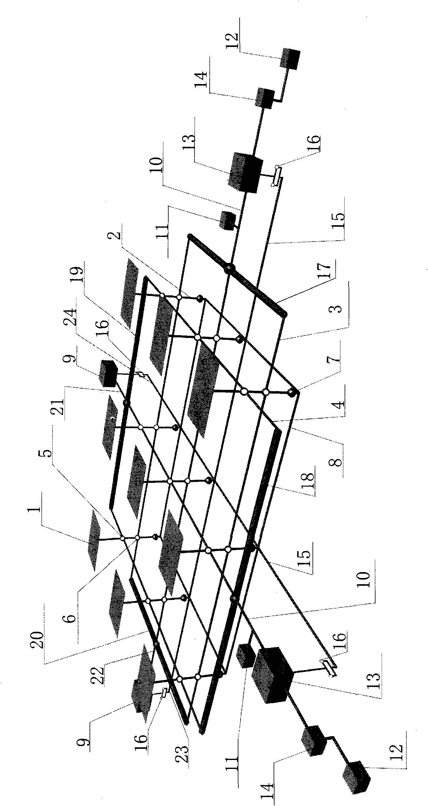
[0074] The device structure of the first embodiment of the mechanism for tracking the sun of the present invention is as follows: figure 1 For the sake of simplicity and clarity of drawing, figure 1 Only the frame array structure of 3 rows × 3 columns is drawn in the figure. The solar light receiving device in the figure is a reflector. In fact, the number of rows and columns can be any number. The receiving device can be a reflector or a lens assembly or a reflector and a lens. The combination or solar photovoltaic cell module including concentrator cell module or thermal energy receiver etc., figure 1 The middle device includes 9 solar light receiving devices 1, 9 vertical columns 2 which are divided into two sections for supporting the solar light receiving device, 3 row push-pull rods 3 parallel to each other and located on the same plane, and 3 columns parallel to each other and located on the same plane. Push-pull rod 4, 9 hinges 5 of row push-pull rod 4 and column 2, 9...

Embodiment 2

[0095] The device structure of the second embodiment of the mechanism for tracking the sun of the present invention is as follows Figure 10 and Figure 11 , Figure 12 shown, where Figure 10 is a schematic diagram of a plurality of solar light receiving devices (here, flat mirrors) arranged in a row, Figure 10 In the middle 49 is the row rotating shaft, 50 is the row rotating shaft, 51 and 52 are the bearings, the arrangement method is the same as that of the first embodiment, the difference is that in the second embodiment, the rotating shaft 49 and the rotating shaft 50 and the bearings 51 and 52 are used instead. The row push-pull rods 3 and column push-pull rods 4 in the first embodiment, as well as the hinges 5 and 6 of the row and column push-pull rods and the upright column 2, combine several such as Figure 10 The solar light receiving devices shown in a row are combined to form a Figure 11 the frame array shown, Figure 12 It is a schematic diagram of the con...

Embodiment 3

[0098] The device structure of the third embodiment of the mechanism for tracking the sun of the present invention is as follows: Figure 13 and Figure 14 , Figure 15 shown, where Figure 13 It is a schematic diagram of a plurality of solar light receiving devices arranged in a row (for simplicity, it is drawn as a plane mirror), Figure 14 for multiple lines as above Figure 13 Schematic representation of the receiving unit actuated with a push-pull rod, Figure 15 for multiple lines as above Figure 13 Schematic representation of the receiving device being actuated with three push-pull rods.

[0099] Figure 13 The middle 61 is the rotating shaft and the push-pull rod, and the 62 is the push-pull rod.

[0100] Figure 14 59 is a cylinder pair, 63 is a connecting rod, 64 is a rocker, the driver and the linkage mechanism connected with the push-pull rod 62 are respectively installed on a one-dimensional steering bracket, and its rotating shaft is perpendicular to the...


PUM


Abstract

The invention relates to an automatic sun tracking device, and belongs to the technical field of solar utilization. The device comprises a condensation module array, a drive mechanism, a tracking control circuit, a sensor and the like. A set of control and drive mechanism controls and drives hundreds of to tens of thousands of sunlight receiving devices to track the sun; and the receiving devices comprise a condensation or non-condensation photovoltaic cell assembly, a heat energy receiving device, a sunlight reflector, a sunlight refractor and the like and are used for photovoltaic power generation or heat energy application and used for reflecting or refracting the sunlight to a receiver on a tower for photovoltaic power generation or heat energy application and the like. The device has simple structure, is not easy to deform, has good wind resistance, high tracking precision and low cost, and can be used for various solar utilization systems.

Description

technical field [0001] The invention relates to a mechanism for tracking the sun and its application, and belongs to the technical field of solar energy utilization. Background technique [0002] Using low cost and simple methods is very important for sun tracking and concentrating solar energy utilization. For this reason, many people at home and abroad have proposed many methods and mechanisms for tracking the sun. These technologies can be attributed to the following five categories: [0003] One is to use a set of control and transmission system to control a solar receiver, this method is the simplest, but the cost is very expensive; [0004] The second is to use a set of control and transmission system to control the condensing of multiple cylindrical condensers, which is a single-axis tracking condensing. The condensing area of ​​this method is a focal line area, which cannot generate high temperature and has a medium cost; [0005] The third is to use a set of contro...

Claims


Application Information

Patent Timeline
IPC IPC(8): G05D3/00
Inventor 邱定平
Owner 邱定平
Why Eureka
Try Eureka