Method for eliminating spatial hole-burning effect through driving solid laser gain medium
A solid-state laser, gain medium technology, applied in excitation methods/devices, laser parts and other directions, can solve problems such as adjustment difficulties, achieve the effects of simple and effective methods, elimination of multi-mode competition, and improved output performance
- Summary
- Abstract
- Description
- Claims
- Application Information
AI Technical Summary
Problems solved by technology
Method used
Image
Examples
Embodiment 1
[0025] Embodiment 1: (device embodiment)
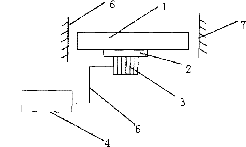
[0026] Such as figure 1 As shown, a device for eliminating the spatial hole-burning effect by driving the gain medium of the solid-state laser comprises a solid-state laser, piezoelectric ceramics 3 and a drive circuit 4, and is characterized in that the piezoelectric ceramics 4 are strip-shaped and fixed at the solid-state laser gain On the base 2 under the medium 1, the axial direction of the piezoelectric ceramic 3 is consistent with the axial direction of the gain medium 1; the driving circuit 4 is a circuit for generating a triangular wave signal, and its signal output terminal is connected to the piezoelectric ceramic 4 through a wire 5, because The inverse piezoelectric effect of the piezoelectric ceramic 4 is the electrostrictive effect. The axial expansion and contraction of the piezoelectric ceramic 4 causes the gain medium 1 of the solid-state laser to produce a λ / 4 displacement along the axial direction, so that the gain ...
Embodiment 2
[0030] Embodiment 2: (method embodiment)
[0031] A method for eliminating the spatial hole-burning effect of a solid-state laser by using the above-mentioned device, the steps are as follows:
[0032] 1. Turn on the power of the solid-state laser to make it work normally; place the laser power measurement device at the output end of the solid-state laser for power measurement;
[0033] 2. Connect the triangular wave signal output terminal of the driving circuit 4 to the piezoelectric ceramic 3 through the wire 5, and turn on the power supply of the driving circuit 4, so that the driving circuit 4 generates a stable triangular wave signal;
[0034] 3. Adjust the frequency of the drive circuit 4, and observe whether there is a change in the output power by the laser power measuring device. If there is no power change, slowly increase the voltage value of the drive circuit 4, and then adjust the frequency of the drive circuit 4. When the laser power When the measurement device ...
PUM
 Abstract
Description
Claims
Application Information
 - R&D
- Intellectual Property
- Life Sciences
- Materials
- Tech Scout
- Unparalleled Data Quality
- Higher Quality Content
- 60% Fewer Hallucinations
Browse by: Latest US Patents, China's latest patents, Technical Efficacy Thesaurus, Application Domain, Technology Topic, Popular Technical Reports.
© 2025 PatSnap. All rights reserved.Legal|Privacy policy|Modern Slavery Act Transparency Statement|Sitemap|About US| Contact US: help@patsnap.com


