Disc brake motor for rotary whirley

A technology of disc brakes and jib cranes, which is applied in the direction of controlling mechanical energy, electrical components, and electromechanical devices, and can solve the problems of installation structure volume, large weight, large axial and radial dimensions, and large occupied space. To achieve the effect of simplified structure, short axial dimension and flexible braking

Inactive Publication Date: 2011-02-16
北京富特盘式电机有限公司
View PDF0 Cites 5 Cited by
  • Summary
  • Abstract
  • Description
  • Claims
  • Application Information

AI Technical Summary

Problems solved by technology

[0002] The original wind power generation equipment uses the traditional electromagnetic brake asynchronous motor for the maintenance of the main engine of the slewing jib crane with wind power. A DC electromagnetic brake is added between the rear end cover of the motor and the fan. The motor and the reducer are assembled separately and are independent of each other. The space area is large, the overall appearance installation structure is bulky and heavy, the axial and radial dimensions are large, the structure is clumsy, and the appearance is not aesthetically pleasing

Method used


Image

  • Disc brake motor for rotary whirley
  • Disc brake motor for rotary whirley

Examples


Embodiment Construction

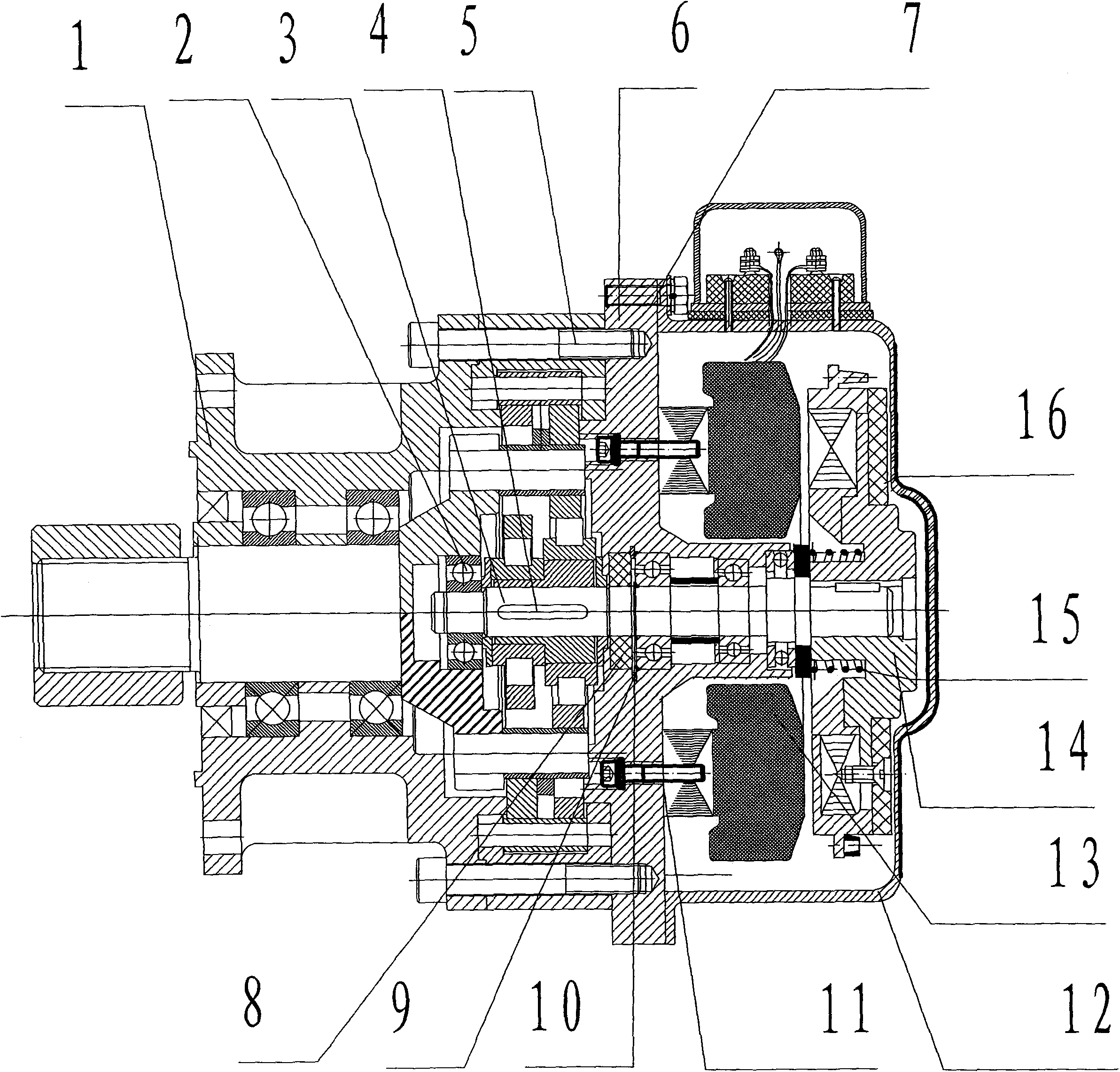
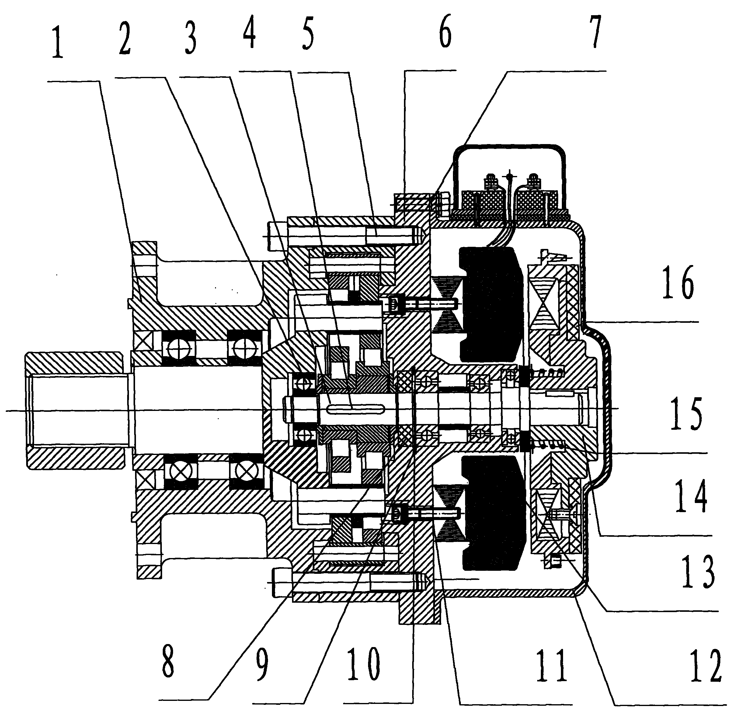
[0012] The schematic cross-sectional view of the YHHP1100 disc brake motor used in the slewing jib crane of the present invention will be described below in conjunction with the accompanying drawings.

[0013] The motor stator 13 and the rotor 14 are in the shape of a disk, and the planar coils are embedded in the slot of the stator core to form the stator winding. The back of the rotor 14 is bonded with a ring-shaped non-asbestos brake pad 16 to form a whole, and the compression spring 15 is installed on the iron core of the rotor 14. In the central groove, the motor casing 12 is connected with the motor frame 6 with the M8×35 hexagonal connection screw 7, covers the stator 13 rotor 14 and maintains a brake clearance with the annular non-asbestos brake pad 16. The motor stator 13 and the motor frame 6 are connected by M8×18 hexagon socket head screws 11, and sealed with HZ703 adhesive sealant to prevent lubricating oil from entering the motor, and evenly apply calcium-based lu...


PUM


Abstract

The invention discloses a disc brake motor which replaces the traditional electromagnetic braking asynchronous motor to be used for a rotary whirley. The disc brake motor is characterized in that the cores of a stator and a rotor are disc-shaped; stator windings embedded in a radial shape and centrifugal cast aluminium conducting bars are arranged at end faces; an annular asbestos-free brake sheet is glued on the back face of the stator; and a brake spring is arranged between the stator and the rotor. The disc brake motor has the function of operating normally under electrification condition and quickly braking at the moment of power failure; the engine base and the rotating shaft of the disc brake motor are arranged to substitute the terminal pad and the rotating shaft of a speed reducer; the disc brake motor is directly embedded into the speed reducer to be combined with the speed reducer into a whole, thus the structure is simplified, the volume of the integral structure is reduced, mechanical and electrical integration is realized, the systematic precision and reliability are enhanced, the length of the original motor and the speed reducer which are connected is shortened to 354mm from 437mm, and the weight is lightened to 53.5kg from 61.6kg; and the invented disc brake motor for a rotary crane hoister has the advantages of novel structure, small size, light weight, short axial and radial dimensions, flexible braking, accurate position and beautiful integral structure.

Description

technical field [0001] The present invention relates to a brake motor for overhauling the main engine of a slewing jib crane for wind power generation. As the capacity of a single unit of wind power generation equipment continues to increase, the difficulty of maintenance and safety hazards increases. Due to the limitation of space in the tower, it is required to provide a Type, novel and compact structure, short axial dimension, small size, light weight, rapid braking, accurate positioning, reliable operation, convenient maintenance, YHHP1100 disc brake motor for slewing jib crane. Background technique [0002] The original wind power generation equipment uses the traditional electromagnetic brake asynchronous motor for the maintenance of the main engine of the slewing jib crane with wind power. A DC electromagnetic brake is added between the rear end cover of the motor and the fan. The motor and the reducer are assembled separately and are independent of each other. The sp...

Claims


Application Information

Patent Timeline
Patent Type & Authority Applications(China)
IPC IPC(8): H02K5/04H02K7/12
Inventor 王东林高淑立
Owner 北京富特盘式电机有限公司
Why Eureka
Try Eureka