Drive bootstrap circuit for switching tube of switching power supply converter

A technology of bootstrap circuit and switching power supply

Inactive Publication Date: 2011-02-16
SHANGHAI JIAO TONG UNIV
View PDF3 Cites 14 Cited by
  • Summary
  • Abstract
  • Description
  • Claims
  • Application Information

AI Technical Summary

Problems solved by technology

However, the PMOS transistor itself also has insurmountable shortcomings: because the mobility of the PMOS transistor is only about one-third of that of the NMOS, if the |V of the two GS -V T |Same as the conduction loss, the size of the PMOS power switch is much larger than that of the NMOS power switch, occupying a considerable part of the chip area

Method used


Image

  • Drive bootstrap circuit for switching tube of switching power supply converter
  • Drive bootstrap circuit for switching tube of switching power supply converter
  • Drive bootstrap circuit for switching tube of switching power supply converter

Examples


Embodiment Construction

[0016] The embodiments of the present invention are described in detail below. This embodiment is implemented on the premise of the technical solution of the present invention, and detailed implementation methods and specific operating procedures are provided, but the protection scope of the present invention is not limited to the following implementation example.

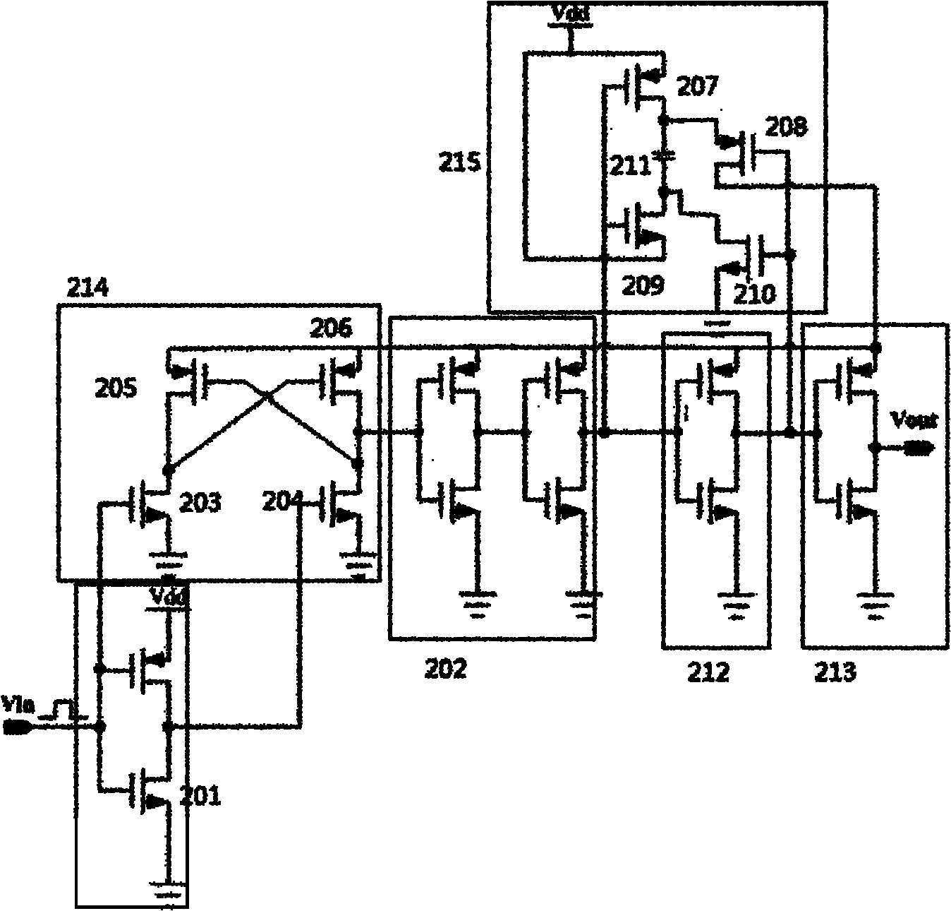
[0017] Such as figure 2 As shown, this embodiment includes: a bootstrap capacitor 211, a low-voltage CMOS inverter 201, three high-voltage CMOS inverters 202, 212, and 123, a MOS tube voltage conversion mechanism 214, and a switch conduction mechanism 215, in:

[0018] The input end of the low-voltage CMOS inverter 201 is connected to the input power supply, the output end of the low-voltage CMOS inverter 201 is connected to the MOS tube voltage conversion mechanism 214 in turn, and three high-voltage CMOS inverters 202, 212, and 123 are in phase In series, the positive terminals of the MOS tube voltage conversi...


PUM


Abstract

The invention discloses a drive bootstrap circuit for a switching tube of a switching power supply converter, belonging to the filed of semiconductor technology, and comprising a bootstrap capacitor, a low-voltage CMOS inverter, three high-voltage CMOS inverters, an MOS tube voltage switching mechanism and a switch breakover mechanism. The device further improves the grid control voltage of a power tube so as to reduce the breakover resistance of a power switching tube from the aspect of circuit structure.

Description

technical field [0001] The invention relates to a device in the technical field of semiconductors, in particular to a switching power converter switching tube driving bootstrap circuit. Background technique [0002] Along with the energy-saving requirements of portable electronic products and the technical difficulties in heat dissipation of portable electronic products, higher and higher requirements are put forward for the power management chips, especially the efficiency requirements in the voltage conversion process. Among them, the wide application of switching power supply management is just to adapt to the high efficiency and energy saving requirements of this contemporary electronic consumer products, breaking through the bottleneck of low efficiency and inability to achieve boost management that cannot be broken through by linear power supply management. Even the change of power management mode achieves a step most important improvement in efficiency, and changes th...

Claims


Application Information

Patent Timeline
Patent Type & Authority Applications(China)
IPC IPC(8): H02M1/08
Inventor 褚敏戴庆元金梓才
Owner SHANGHAI JIAO TONG UNIV
Why Eureka
Try Eureka