Supercharge Your Innovation With Domain-Expert AI Agents!

Photovoltaic assembly junction box

A photovoltaic module and junction box technology, applied in photovoltaic modules, photovoltaic power generation, electrical components, etc., can solve the problems of burnt-out components, urgent demand for junction boxes, and failure of sealing performance, so as to enhance the heat dissipation capacity and solve the problem that the power cannot be increased , The effect of solving the sealing problem

Inactive Publication Date: 2012-10-10
苏州固锝新能源科技有限公司
View PDF0 Cites 0 Cited by
  • Summary
  • Abstract
  • Description
  • Claims
  • Application Information

AI Technical Summary

Problems solved by technology

If the junction box is damaged or the connection is not reliable, the junction box will not work properly, so when the solar module is partially covered, the entire solar module system will not work normally, and the covered part will emit a lot of heat, which will burn the module seriously
At present, the working circuit of the junction box of the photovoltaic module is placed in the sealed junction box. When the junction box of the photovoltaic module is in the working state, the bypass diode will generate a high temperature (up to 200 degrees), so that the air in the sealed box will sharply Expansion, which leads to the failure of sealing performance, and the plastic shell cannot withstand high temperature and high pressure, resulting in deformation and burning
On the other hand, with the development of science and technology, the conversion efficiency of photovoltaic cells is increasing day by day, the power of photovoltaic cells is increasing, and the demand for high-power photovoltaic module junction boxes is becoming increasingly urgent. The above-mentioned junction boxes make existing photovoltaic modules The power of the junction box cannot be increased, resulting in a technical bottleneck

Method used


Image

  • Photovoltaic assembly junction box
  • Photovoltaic assembly junction box
  • Photovoltaic assembly junction box

Examples


Embodiment Construction

[0019] The preferred embodiments of the present invention will be described in detail below in conjunction with the accompanying drawings, so that the advantages and features of the present invention can be more easily understood by those skilled in the art, so as to define the protection scope of the present invention more clearly.

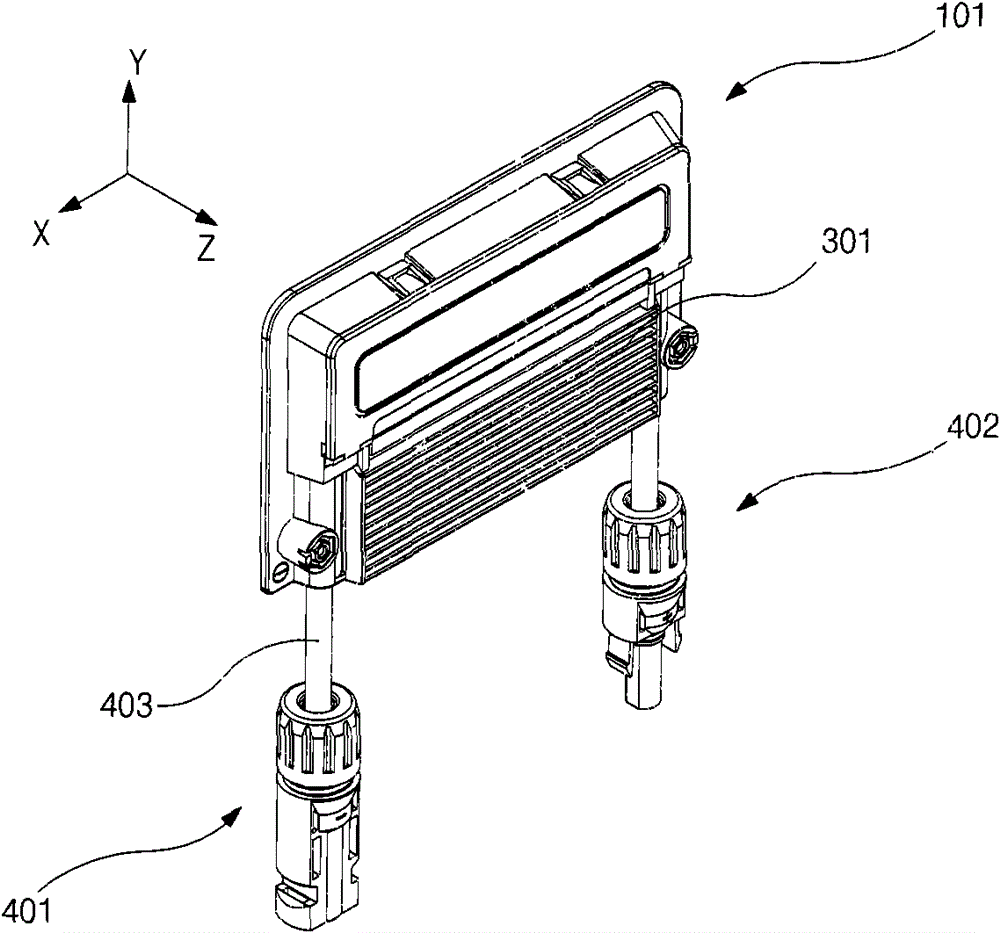
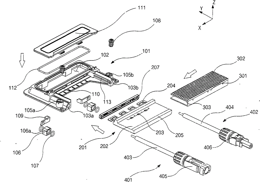
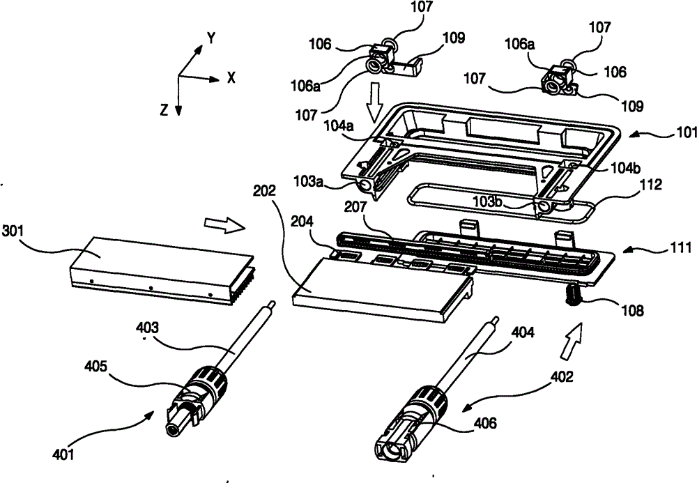
[0020] See attached figure 1 To attach image 3 The photovoltaic module junction box in this embodiment includes a junction box body 101, a working circuit module 201, a heat dissipation module 301, and connection modules 401, 402. The junction box body 101 can be molded from a plastic material at one time, and the heat dissipation module 301 can be made of a metal material.

[0021] as attached figure 2 with attached image 3 As shown, the junction box body 101 includes a side wall extending in the Z-axis direction and closed around the Z-axis. The bottom end of the side wall extends in the XY plane to form a flange, and the flange is attache...


PUM


Abstract

The invention discloses a photovoltaic assembly junction box which comprises a junction box body, an operating circuit module, a heat dissipating module and a connecting module, wherein the junction box body is provided with an accommodating cavity, and the accommodating cavity is isolated from the outside in a gas-liquid sealing mode; the operating circuit module comprises an operating circuit and a plurality of pins electrically connected with the operating circuit, the operating circuit is arranged outside the accommodating cavity, and the pins are arranged inside the accommodating cavity;the heat dissipating module is arranged outside the operating circuit; the connecting module comprises a positive connecting device and a negative connecting device, and the positive connecting device and the negative connecting device are respectively and electrically connected with the corresponding pin inside the accommodating cavity. The heat dissipation capability of the photovoltaic assembly junction box is greatly enhanced; thus, the invention not only solves the sealing problem in the prior art, but also solves the technical problem that power can not be increased.

Description

technical field [0001] The invention relates to a junction box of a photovoltaic module. Background technique [0002] Photovoltaic cells are devices that directly convert solar radiation energy into electrical energy. Photovoltaic modules are products that are connected and packaged by multiple photovoltaic cells. They are the basic units of battery arrays in photovoltaic power generation systems. Photovoltaic module junction box is the key connection device of the solar module system. The function of the junction box is to prevent the hot spot effect when the solar module is partially blocked. If the junction box is damaged or the connection is not reliable, the junction box will not work properly, so when the solar module is partially covered, the entire solar module system will not work normally, and the covered part will emit a lot of heat, which will burn the module seriously . At present, the working circuit of the junction box of the photovoltaic module is placed i...

Claims


Application Information

Patent Timeline
Patent Type & Authority Patents(China)
IPC IPC(8): H02N6/00H02G3/08
CPCH01L31/0485Y02E10/50H02S40/34
Inventor 陈新初
Owner 苏州固锝新能源科技有限公司
Features
  • R&D
  • Intellectual Property
  • Life Sciences
  • Materials
  • Tech Scout
  • Unparalleled Data Quality
  • Higher Quality Content
  • 60% Fewer Hallucinations
Learn More