Low-power consumption power carrier communication circuit and method

A technology of power carrier communication and low power consumption, applied in the direction of distribution line transmission system, can solve problems such as loss and reduce system sensitivity, and achieve the effect of reducing power consumption and flexible design

Inactive Publication Date: 2011-02-16
HI TREND TECH SHANGHAI
View PDF3 Cites 9 Cited by
  • Summary
  • Abstract
  • Description
  • Claims
  • Application Information

AI Technical Summary

Problems solved by technology

In addition, the insertion loss of the ceramic filter is usually more than 6dB, so the sign

Method used


Image

  • Low-power consumption power carrier communication circuit and method
  • Low-power consumption power carrier communication circuit and method
  • Low-power consumption power carrier communication circuit and method

Examples


Embodiment Construction

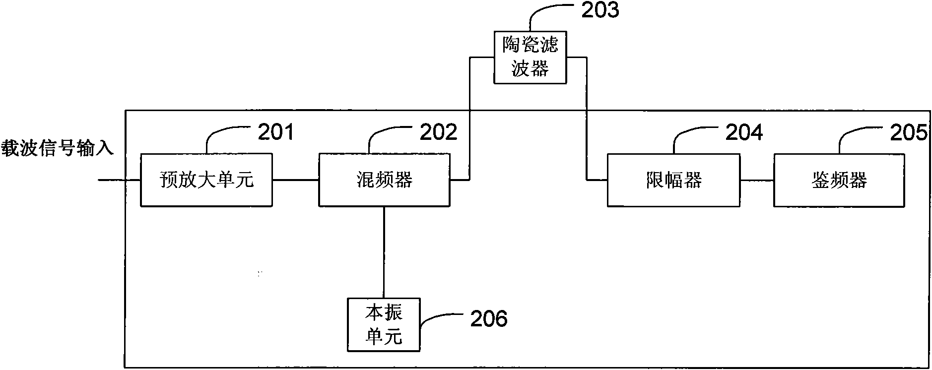
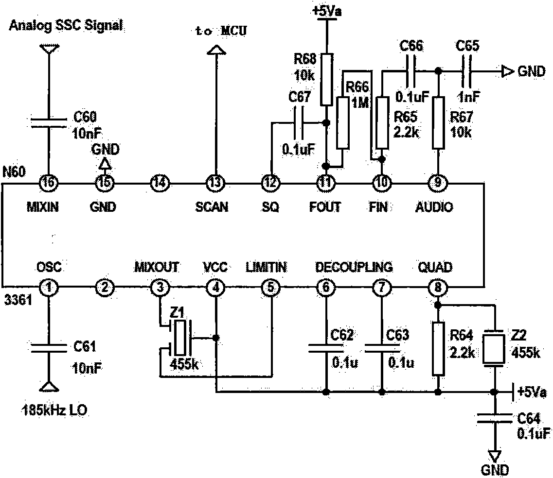
[0027] see image 3 , the low-power power carrier communication circuit of the present invention includes: an on-chip part integrated on the same chip, which is used to perform processing including frequency mixing, band-pass filtering and demodulation on the carrier signal coupled externally to obtain The communication information carried by the carrier signal, wherein the device for band-pass filtering is completely on the chip.

[0028] In this embodiment, the carrier signal input to the on-chip part is processed by the off-chip part, which uses a signal coupler 401 and a band-pass filter 402 to process the signal transmitted on the power line. Wherein, the signal coupler 401 may be, but not limited to, a transformer. The band-pass filter 402 uses a simple inductance-capacitance circuit to filter out 50Hz power frequency grid signals and other out-of-band interferences.

[0029] The on-chip part is used for various processing such as frequency mixing, band-pass filtering,...


PUM


Abstract

The invention provides a low-power consumption power carrier communication circuit and a low-power consumption power carrier communication method. The circuit comprises an on-chip part which is integrated on the same chip; and the on-chip part is used for performing processing such as frequency mixing, band-pass filtering and modulation on an externally coupled carrier signal so as to acquire communication information carried by the carrier signal. The on-chip part can comprise a frequency mixer, an active band-pass filter, a modulator and the like; in addition, an input signal strength indicating circuit and a sleep-mode control unit can also be configured on the chip for controlling the working mode of a high-power consumption device (such as a modulator and the like) on the chip, so that the power consumption can be effectively reduced; and by adopting the active band-pass filter, an off-chip ceramic filter can be saved, the cost can be effectively reduced and the flexibility of design is improved.

Description

technical field [0001] The invention relates to a power carrier communication circuit, in particular to a low power consumption power carrier communication circuit and method. Background technique [0002] The carrier frequency distribution range used by power line carrier communication is: Europe (CENELEC): 3-148.5KHz, North America (FCC): 100-450kHz. In this communication mode, the signal attenuation is large and the noise interference is strong. For such complex communication conditions, the usual power line carrier receiving circuit is a circuit with a heterodyne structure. [0003] like Figure 1A and Figure 1B As shown, this is the receiver front-end circuit architecture of a company that is more influential in the field of power line carrier. Among them, Figure 1A is a schematic diagram of the functional modules of the front-end circuit of the receiver, Figure 1B The specific circuit diagram of the front-end circuit of the receiver. like Figure 1A As shown, the...

Claims


Application Information

Patent Timeline
IPC IPC(8): H04B3/54
Inventor 邓霜
Owner HI TREND TECH SHANGHAI
Why Eureka
Try Eureka