
Cooling treatment system and cooling treatment method of molten slag

A processing device and processing method technology, which is applied in the field of slag product manufacturing, can solve the problems of reducing water retention, inability to effectively use the drum surface for cooling treatment, and inability to meet the granularity of coarse aggregate or roadbed materials, etc.

Active Publication Date: 2011-02-16
JFE STEEL CORP
View PDF1 Cites 7 Cited by
  • Summary
  • Abstract
  • Description
  • Claims
  • Application Information

AI Technical Summary

Problems solved by technology

[0010] (a) Basicity (mass ratio %CaO / %SiO 2 ) (hereinafter referred to as "basicity") higher slag viscosity is high, in the case of cooling treatment of such high viscosity slag with the existing double-drum slag cooling treatment device, due to the high viscosity This makes it difficult for the slag to evenly adhere to the surface of the cooling drum, so it is impossible to effectively use the entire cooling process of the drum surface.
Therefore, the cooling efficiency of slag is low, and high productivity cannot be obtained
In addition, slag with high basicity (especially basicity ≥ 3) is easy to pulverize, and it can be difficult to pulverize such slag by quenching it from the molten state, but after cooling treatment with the existing slag cooling treatment device In the case of high viscosity, the thickness cannot be thinned, and a sufficient cooling rate cannot be obtained, so the pulverization after cooling cannot be properly suppressed
[0011] (b) In the case of cooling relatively low-viscosity molten slag such as blast furnace slag with the conventional double-drum slag cooling device, only a relatively thin slag solidified body with a thickness of about 2 to 3 mm can be obtained, And even if they are crushed into granules, they cannot meet the required particle size of coarse aggregate or roadbed materials.
In addition, in order to make the thinner slag solidified into glass, the water retention will be reduced, and it can be said that it is not suitable for roadbed materials, etc.

Method used


Image

  • Cooling treatment system and cooling treatment method of molten slag
  • Cooling treatment system and cooling treatment method of molten slag
  • Cooling treatment system and cooling treatment method of molten slag

Examples


Embodiment Construction

[0067] In the molten slag cooling treatment device and cooling treatment method of the present invention, the type of slag to be cooled is not limited. For example, blast furnace slag, steelmaking slag (such as converter decarburization slag, dephosphorization slag, desulfurization slag, electric furnace slag, foundry slag, etc.), smelting reduction slag (such as slag produced by smelting reduction of iron ore, Cr ore, Ni ore, Mn ore, etc.), other slags produced from smelting furnaces or refining furnaces, Various slags such as waste incineration slag and waste gasification slag are applicable.

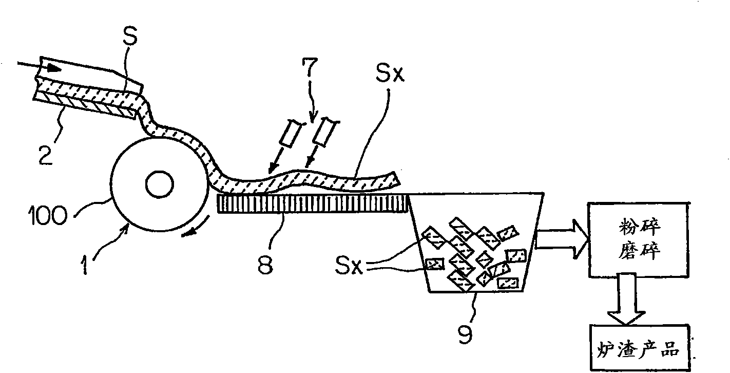
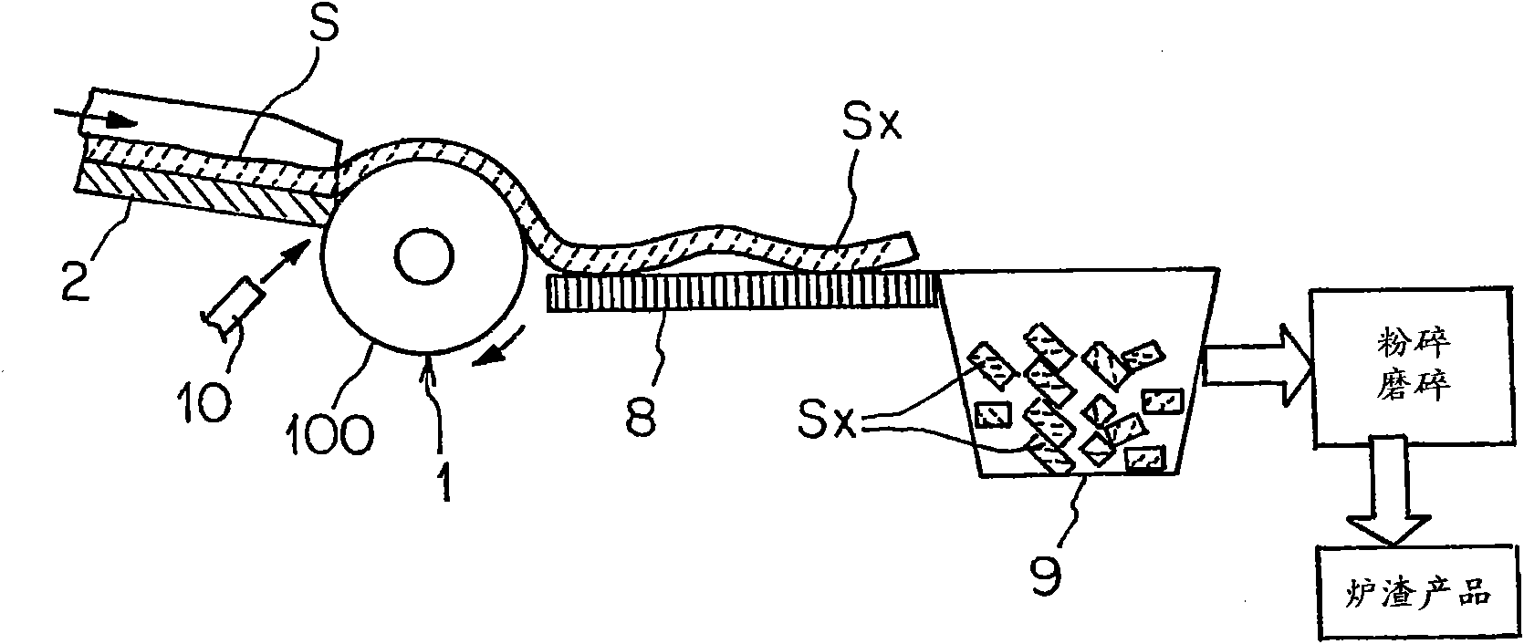
[0068] figure 1 It is a front view schematically showing one embodiment of the slag cooling treatment apparatus and cooling treatment method of the present invention.

[0069] This slag cooling treatment device includes: a rotatable horizontal cooling drum 1 (hereinafter simply referred to as "cooling drum 1"; the same applies to other embodiments), which makes the slag adhere to the...


PUM


Abstract

Provided is a cooling treatment system of molten slag which enables a mass treatment of molten slag without causing damage to a cooling drum due to the drop load of molten slag, and can facilitate handling and post-treatment of cooling treated slag. The cooling treatment system of molten slag comprises a single rotatable horizontal cooling drum (1) which cools molten slag by sticking the molten slag to the outer circumferential drum surface (100), and a gutter (2) for supplying molten slag to the horizontal cooling drum (1), wherein the slag cooled while sticking to the drum surface (100) is separated therefrom as the horizontal cooling drum (1) rotates and discharged in one direction. Since the molten slag is poured through the gutter (2), the drop load of molten slag is not applied to the cooling drum (1), and, since the cooling treated slag is discharged in one direction, handling and post-treatment of cooling treated slag are facilitated.

Description

technical field [0001] The present invention relates to a cooling drum type molten slag cooling treatment device, a method for cooling molten slag using the device, and a method for manufacturing slag products. Background technique [0002] The molten slag (for example, steelmaking slag) generated in the steel manufacturing process is often left to cool in a cooling field, and then cooled by sprinkling water. In addition, there is also a method of spraying water into an iron container called a disk cooling method. [0003] On the other hand, as an apparatus for cooling slag such as blast furnace slag and waste incineration ash slag, a double-drum slag cooling apparatus is known (for example, Japanese Patent No. 3613106). This slag cooling treatment device is equipped with a pair of cooling drums, the pair of cooling drums are parallel in the horizontal direction, and have a rotation direction in which the opposing outer peripheral parts rotate upwards, and the cooling drums...

Claims


Application Information

Patent Timeline
IPC IPC(8): C04B5/00F23J1/00
CPCC04B5/06F23J2900/01002F23J2900/01003F23J1/08C21B2400/026C21B2400/042C21B2400/052C21B2400/056C21B2400/08
Inventor 岩崎克博当房博幸薮田和哉
Owner JFE STEEL CORP
Learn More