Corrosion protection using carbon coated electron collector for lithium-ion battery with molten salt electrolyte

a lithium-ion battery and carbon coating technology, applied in the field of batteries, can solve the problems of significantly reducing the lifetime of the battery, affecting the service life of the battery, and affecting the service life of the battery, and none of them are related to carbon coating electron collectors

Inactive Publication Date: 2008-03-25
TOYOTA MOTOR CO LTD +2
View PDF22 Cites 55 Cited by
  • Summary
  • Abstract
  • Description
  • Claims
  • Application Information

AI Technical Summary

Problems solved by technology

However, corrosion of the electron collector severely affects the performance of batteries having a molten salt electrolyte, degrading cycling ability and high rate performance.
Corrosion results from the oxidation of the molten salt electrolyte on the surface of the metal collector, typically aluminum (Al) or iron (Fe), during charge or discharge.
The corrosion can significantly reduce the lifetime of the battery.
However, none of them are related to carbon coated electron collectors with a Li-ion battery with molten salt electrolyte.

Method used


Image

  • Corrosion protection using carbon coated electron collector for lithium-ion battery with molten salt electrolyte
  • Corrosion protection using carbon coated electron collector for lithium-ion battery with molten salt electrolyte
  • Corrosion protection using carbon coated electron collector for lithium-ion battery with molten salt electrolyte

Examples


example 1

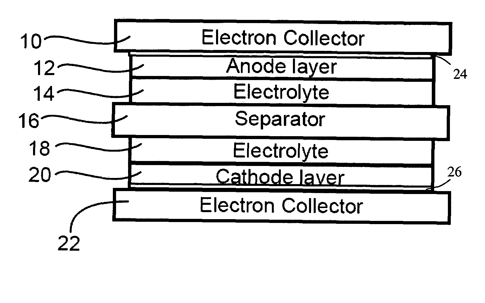
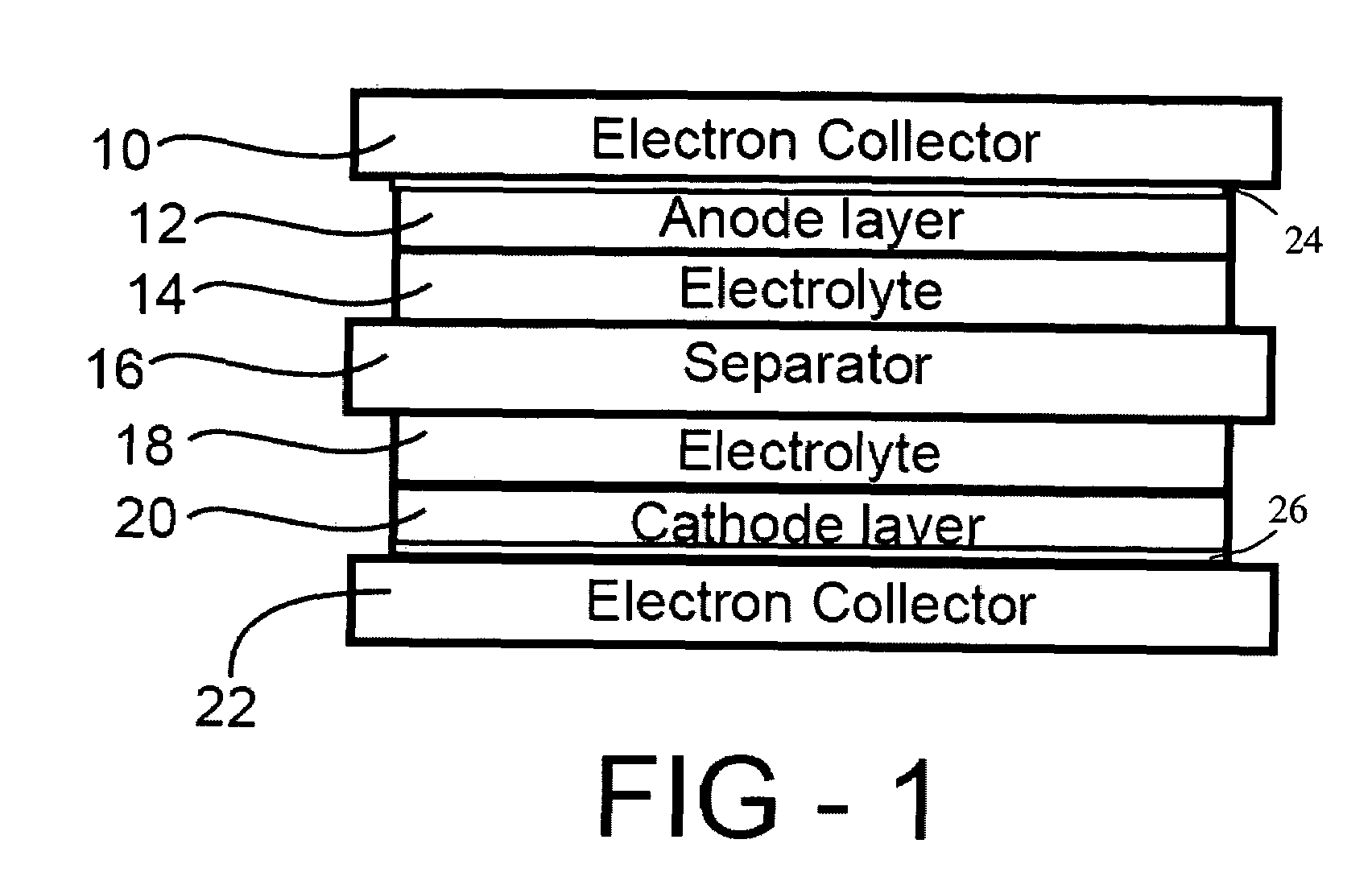
[0019]Positive electrode was fabricated by intimately mixing 85 wt % LiCoO2 powder, 10 wt % carbon powder, and 5 wt % solvent of polyvinylidene fluoride in N-methylpyrrolidone. To form the positive electrode film, the mixed slurry was cast onto aluminum foil (coated or uncoated with carbon) by using doctor blade and dried at 80° C. for 30 minutes.

[0020]A negative electrode was fabricated by intimately mixing 85 wt % Li4Ti5O12 powder, 10 wt % carbon powder, and 5 wt % solvent of polyvinylidene fluoride in N-methylpyrrolidone. To form negative electrode film, the mixed slurry was cast onto aluminum foil (coated or uncoated with carbon) by using doctor blade and dried at 80° C. for 30 minutes.

[0021]The positive electrode sheet, a micro-porous polypropylene film separator, and the negative electrode sheet were stacked, and placed in aluminum laminate pack. A certain amount of the MPI-FSI molten salt electrolyte was added in to the laminate pack. Here, methyl-propyl-imidazolium-bis-fluor...

example 2

[0022]Positive electrode was fabricated by intimately mixing 85 wt % LiCoO2 powder, 10 wt % carbon powder, and 5 wt % solvent of polyvinylidene fluoride in N-methylpyrrolidone. To form the positive electrode film, the mixed slurry was cast onto aluminum foil (coated or uncoated with carbon) by using doctor blade and dried at 80° C. for 30 minutes.

[0023]A negative electrode was fabricated by intimately mixing 85 wt % Li4Ti5O12 powder, 10 wt % carbon powder, and 5 wt % solvent of polyvinylidene fluoride in N-methylpyrrolidone. To form negative electrode film, the mixed slurry was cast onto aluminum foil (coated or uncoated with carbon) by using doctor blade and dried at 80° C. for 30 minutes.

[0024]The positive electrode sheet, a micro-porous polypropylene film separator, and the negative electrode sheet were stacked, and placed in aluminum laminate pack. A certain amount of molten salt electrolyte was added in to the laminate pack. Here, ethyl-1-methyl-3-imidazolium-bis-fluoro-sulfony...


PUM

PropertyMeasurementUnit
electrically conductingaaaaaaaaaa
electron-conductingaaaaaaaaaa
corrosionaaaaaaaaaa

Abstract

A battery, such as a lithium-ion battery, comprises a first electrode, a second electrode, a molten salt electrolyte, and an electron collector, associated with the first electrode, the electron collector comprising an electrically conducting film. The battery further includes a protection layer separating the electron collector and the first electrode, the protection layer comprising a carbon-containing material. The electron collector may be an electrically conducting material such as aluminum, aluminum alloy, copper, nickel, other metal (such as alloys), conducting polymer, and the like. In one example, the protection layer is a graphite layer. In other examples, the protection layer may be a fullerene film, carbon nanotube film, or other carbon-containing material.

Description

REFERENCE TO RELATED APPLICATION[0001]This application claims priority to U.S. Provisional Patent Application Ser. No. 60 / 553,443, filed Mar. 16, 2004, the entire content of which are incorporated herein by reference.FIELD OF THE INVENTION[0002]The present invention relates to batteries, in particular to electron collectors for batteries.BACKGROUND OF THE INVENTION[0003]Molten salt electrolytes are considered safer than traditional organic electrolytes, especially for automobile applications. However, corrosion of the electron collector severely affects the performance of batteries having a molten salt electrolyte, degrading cycling ability and high rate performance. Corrosion results from the oxidation of the molten salt electrolyte on the surface of the metal collector, typically aluminum (Al) or iron (Fe), during charge or discharge. The corrosion can significantly reduce the lifetime of the battery.[0004]Hence, if corrosion of the electron collector can be reduced, the use of sa...

Claims


Application Information

Patent Timeline
Patent Type & Authority Patents(United States)
IPC IPC(8): H01M2/00H01M4/66H01M10/0561H01M10/0563H01M10/36H01M50/417
CPCB82Y30/00H01M4/661H01M4/667H01M10/0561H01M10/0563H01M4/663H01M2/1653H01M2300/0022Y02E60/10H01M50/417
Inventor LI, WENUKAI, JUNZOAWANO, HIROAKIOYAMA, YUTAKAMATSUI, MASAKIPERRON, GERALDARMAND, MICHAEL B.
Owner TOYOTA MOTOR CO LTD
Why Eureka
Try Eureka