
Piezoelectric fan device and air-cooling apparatus using the piezoelectric fan device

A piezoelectric fan and piezoelectric vibrator technology, which is applied to non-variable pumps, machines/engines, mechanical equipment, etc., can solve the problems that the torque cannot be offset, the load applied by the support body, and the noise is generated, so as to reduce the failure influence, cooling efficiency improvement, and amplitude increase effect

Inactive Publication Date: 2011-02-16
MURATA MFG CO LTD
View PDF7 Cites 12 Cited by
  • Summary
  • Abstract
  • Description
  • Claims
  • Application Information

AI Technical Summary

Problems solved by technology

As a result, there is a problem that the support part is very prone to vibration, and the vibration is transmitted to other parts, thereby adversely affecting the reliability of other parts and contacts
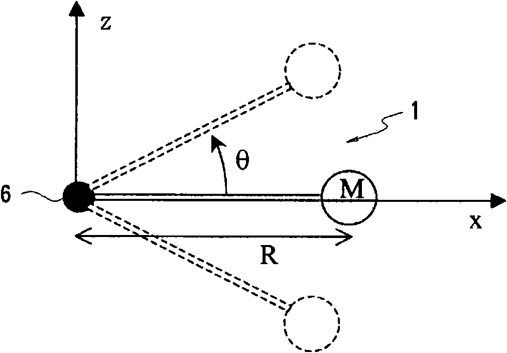
However, the moment about the longitudinal axis cannot be canceled out, thus exerting a load on the support body
Therefore, there is a problem that the support body rotates and vibrates, and the vibration spreads to other parts via the support body, thereby generating noise.
In addition, the so-called vibration of the support body means that part of the vibration energy generated by the piezoelectric fan is lost.

Method used


Image

  • Piezoelectric fan device and air-cooling apparatus using the piezoelectric fan device
  • Piezoelectric fan device and air-cooling apparatus using the piezoelectric fan device
  • Piezoelectric fan device and air-cooling apparatus using the piezoelectric fan device

Examples


Embodiment approach 1

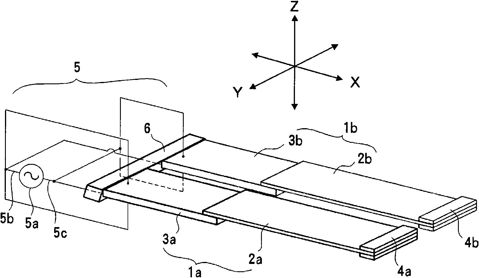
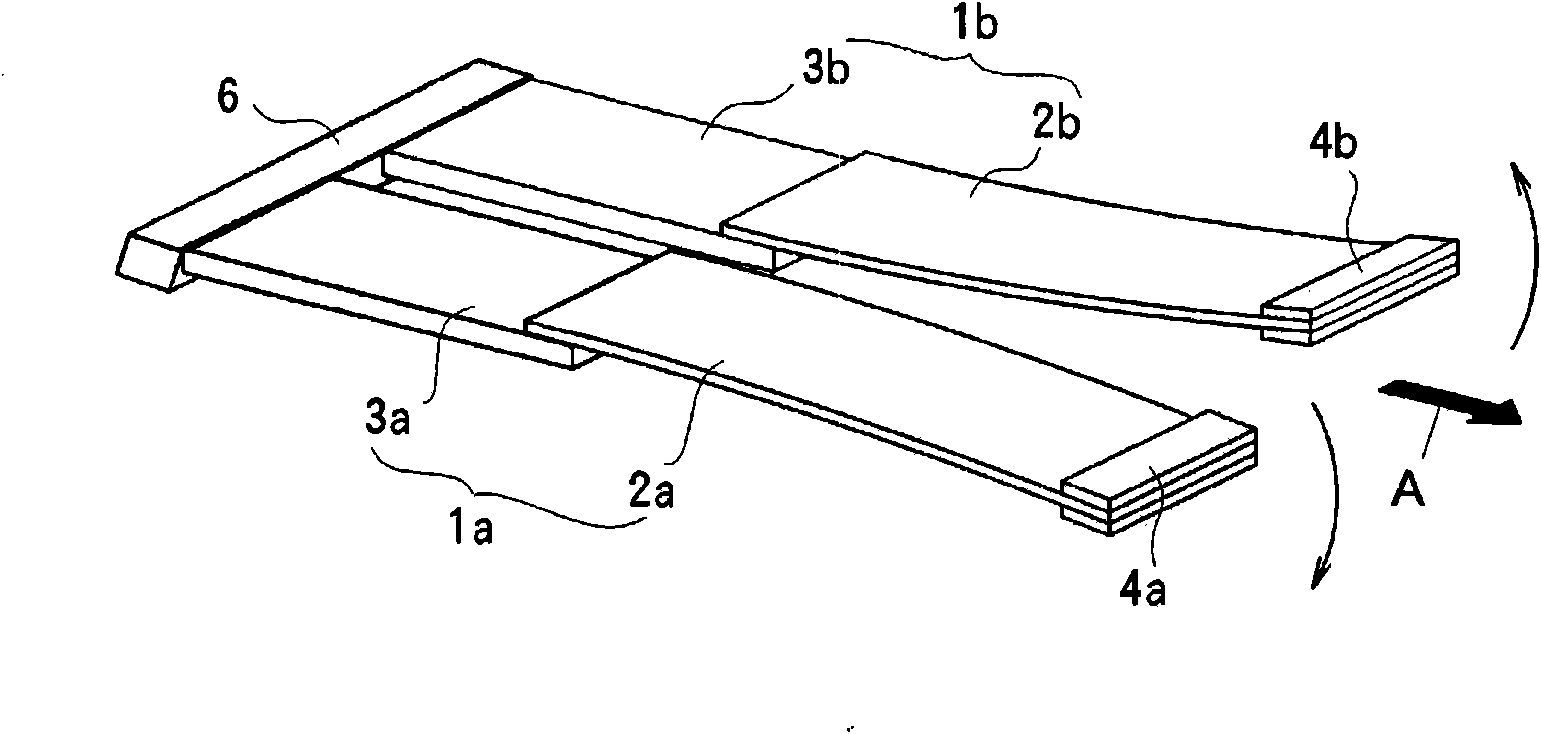
[0053] Figure 4 ~ Figure 7 An example of an air cooling device using Embodiment 1 of the piezoelectric fan device according to the present invention as a heat sink is shown. Figure 4 Among them, four piezoelectric fans 10 a to 10 d having the same vibration characteristics are aligned in the width direction with respect to the support body 11 , and are connected and fixed to the support body 6 at equal intervals. The piezoelectric fans 10a-10d have the same figure 1 The piezoelectric fans 1a, 1b shown are of the same construction. That is, the piezoelectric fans 10a to 10d respectively include a plurality of blades 12a to 12d and a plurality of double-layer piezoelectric type piezoelectric vibrators 13a to 13d, and the plurality of blades 12a to 12d can be freely bent and displaced in the thickness direction. The plurality of piezoelectric vibrators 13a to 13d are connected to one end in the longitudinal direction of each of the blades 12a to 12d, and flexurally vibrate b...


PUM


Abstract

Disclosed is a piezoelectric fan apparatus that uses a plurality of miniaturized piezoelectric fans, and can reduce vibrations that arise in the support unit due to the drive of the piezoelectric oscillators. Four piezoelectric fans (10a-10d) are arranged in a parallel configuration in the widthwise direction, and the ends on the sides opposite to the extending sides of the blades of each piezoelectric fan are connected and supported in a parallel configuration by a support (11). Each piezoelectric fan is provided with a piezoelectric oscillator (13a-13d) which undergoes bending vibrations due to applied voltage, and equipped with a blade (12a-12d) connected to each piezoelectric oscillator so as to be excited by the piezoelectric oscillator. A voltage-applying means (15) is used to drive the two central piezoelectric fans 10b, 10c with the same phase, and since the two piezoelectric fans 10a, 10d at the ends are driven with opposite phase, the center-of-gravity vibrations that act on the support (11) as well as the moment around the three axes are negated.

Description

technical field [0001] The present invention relates to a piezoelectric fan device that bends and vibrates a piezoelectric vibrator to greatly bend and displace a blade connected thereto to discharge air. Background technique [0002] In recent years, as portable electronic equipment, along with miniaturization and high-density mounting of components, measures to dissipate heat generated inside the electronic equipment have become a problem. As a device for efficiently dissipating heat from such electronic devices, an air cooling device using a piezoelectric fan has been proposed. [0003] Patent Document 1 discloses a piezoelectric fan having a structure in which a double-layer piezoelectric vibrator is formed by sandwiching and bonding thin metal plates between a pair of plate-shaped piezoelectric elements. Both ends of the vibrator are attached with elastic thin plates in a perpendicular direction, and the central part of the double-layer piezoelectric vibrator is suppor...

Claims


Application Information

Patent Timeline
Patent Type & Authority Applications(China)
IPC IPC(8): F04D33/00
CPCF04D33/00
Inventor 和田宽昭神谷岳
Owner MURATA MFG CO LTD
Learn More