Hydraulic brake master pump

A technology of hydraulic brake and brake fluid, applied in the direction of hydraulic brake transmission device, etc., can solve the problems of high production and assembly precision requirements, complicated installation, difficult product processing, etc., and achieves rapid and effective hydraulic transmission, simple overall structure, and convenience. The effect of forming

Inactive Publication Date: 2011-02-23
罗定
View PDF8 Cites 2 Cited by
  • Summary
  • Abstract
  • Description
  • Claims
  • Application Information

AI Technical Summary

Problems solved by technology

[0008] However, the improved technical solution still has the following deficiencies: firstly, because the check valve is set at the junction of the large plunger and the small plunger, the production and assembly precision requirements are high, and the assembly is troublesome; secondly, the oil that the check valve can control The pressure is also fixed and cannot adapt to various needs; secondly, the design of the second axial groove is relatively co

Method used


Image

  • Hydraulic brake master pump
  • Hydraulic brake master pump
  • Hydraulic brake master pump

Examples


Example Embodiment

[0019] The present invention will be further described in detail below in conjunction with the embodiments of the drawings.

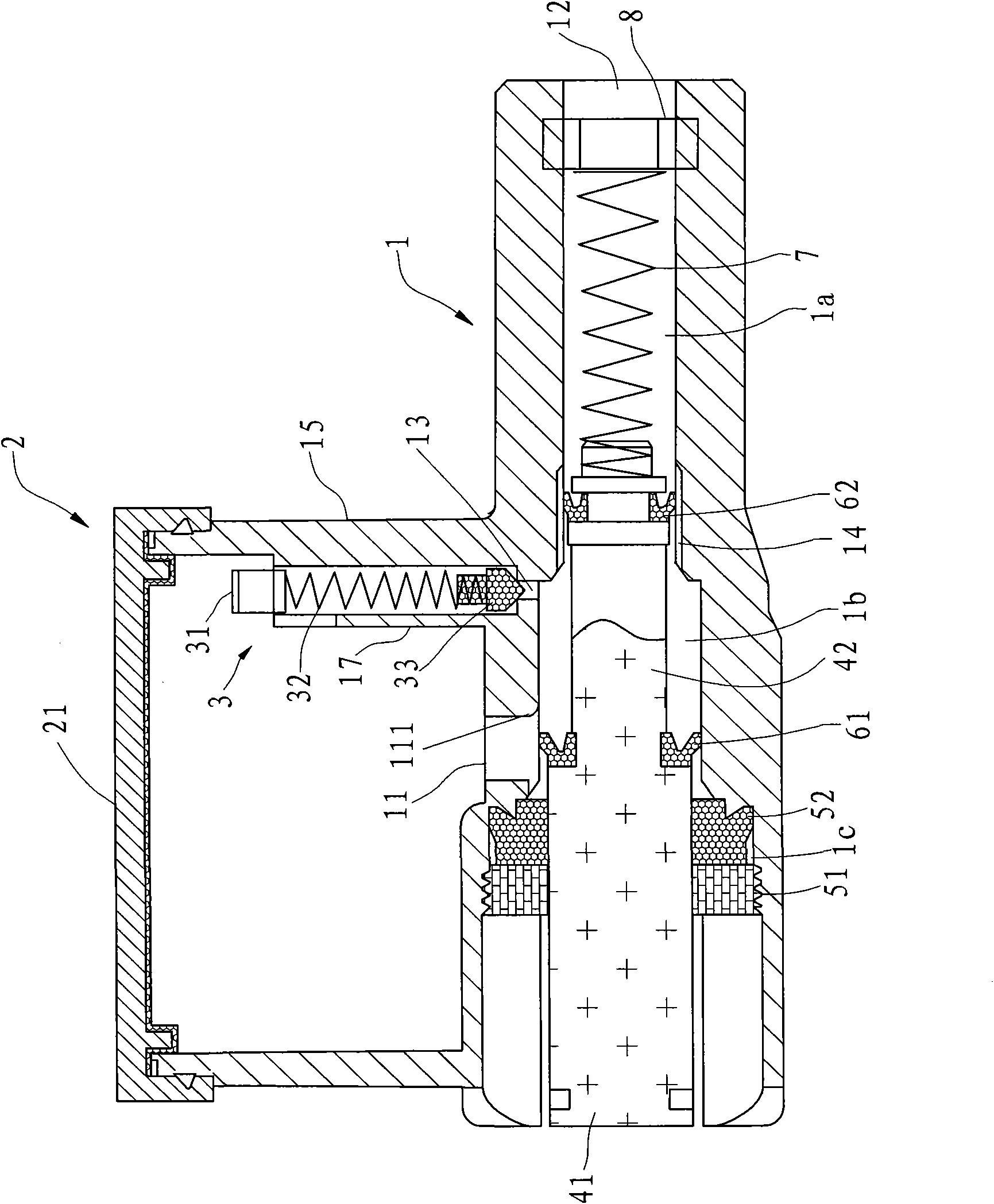
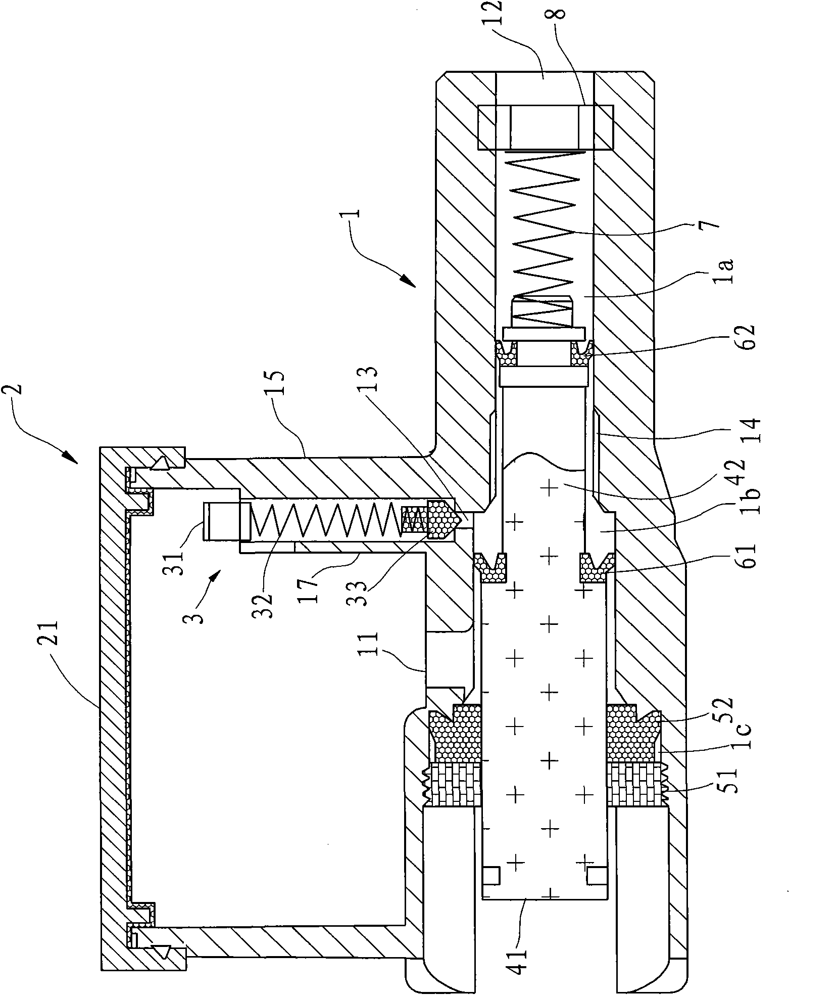
[0020] Such as figure 1 with figure 2 As shown, the hydraulic brake master cylinder in this embodiment includes a pump body 1, an oil cup 2 provided on the pump body 1, a plunger that can move back and forth in the plunger cavity of the pump body 1, a front sealing ring 62, The rear sealing ring 61 and the return spring 7 capable of resetting the plunger. One end of the return spring 7 abuts against the plunger, and the other end is arranged on the spring seat 8. The plunger includes a large plunger 41 and is arranged on the large plunger 41 The small plunger 42, the large plunger 41 and the small plunger 42 at the front end are integrally formed of metal materials. The pump body 1 is formed with a raised surrounding wall 15, the port cover of the surrounding wall 15 is provided with a cup cover 21, and the surrounding wall 15 and the cup cover 21 form an...


PUM


Abstract

The invention discloses a hydraulic brake master pump, which comprises a pump body, an oil cup arranged on the pump body, plunger pistons in a plunger piston cavity, a front sealing ring, a rear sealing ring and a return spring, wherein the plunger pistons comprise a large plunger piston and a small plunger piston integrally formed with the large plunger piston; the front sealing ring and the rear sealing ring are positioned on the small plunger piston and the large plunger piston to divide the plunger piston cavity into a front cavity, a middle cavity and a rear cavity respectively; the pump body is provided with a liquid feeding hole and a liquid outlet, one end of the liquid feeding hole is communicated with the plunger piston cavity, the other end of the liquid feeding hole is communicated with the oil cup, and the liquid outlet is positioned at the front end of the plunger piston cavity; the inner wall of the plunger piston cavity is provided with a first axial groove for communicating the front cavity and the middle cavity; and the pump body is provided with a one-way valve for allowing the brake liquid to flow to the oil cup from the middle cavity. Compared with the prior art, the hydraulic brake master pump has the advantages that: because the one-way valve is independent of the plunger pistons and arranged in the oil cup and the large plunger pistons and the small plunger pistons are formed integrally, the integral structure is simple, and processing and assembly are convenient.

Description

technical field [0001] The invention relates to a brake master cylinder, in particular to a hydraulic brake master cylinder applicable to vehicles such as motorcycles and beach vehicles. Background technique [0002] At present, the hydraulic braking system on motorcycles and ATVs usually consists of operating handles, master cylinders, oil delivery pipes, sub-cylinders, friction plates and brake discs. Among them, the master cylinder includes a pump body, plunger, return spring and oil Cup, such as the "Motorcycle Hydraulic Brake Device" with the China Authorized Announcement No. CN2245030Y discloses such a master cylinder. The spring is located in the plunger chamber of the pump body, and the return spring makes the plunger always have a tendency to move toward the side of the operating handle. At the same time, the pump body is also provided with a liquid outlet hole and a liquid replenishment hole communicating with the plunger chamber. The liquid outlet hole is located...

Claims


Application Information

Patent Timeline
IPC IPC(8): B60T11/16
Inventor 罗定
Owner 罗定
Why Eureka
Try Eureka