Method and system for liquid fuel conditioning

A fuel conditioning and gas fuel technology, which can be used in liquid fuel feeders, charging systems, fuel heat treatment devices, etc., and can solve problems such as complex designs

Inactive Publication Date: 2011-02-23
极限燃烧公司
View PDF3 Cites 4 Cited by
  • Summary
  • Abstract
  • Description
  • Claims
  • Application Information

AI Technical Summary

Problems solved by technology

But even those systems are not free from the drawbacks mentioned above
Also, this level of fuel compression requires more advanced manufacturing techniques, more complex designs and highly trained internal combustion engine maintenance personnel

Method used


Image

  • Method and system for liquid fuel conditioning
  • Method and system for liquid fuel conditioning
  • Method and system for liquid fuel conditioning

Examples


Embodiment Construction

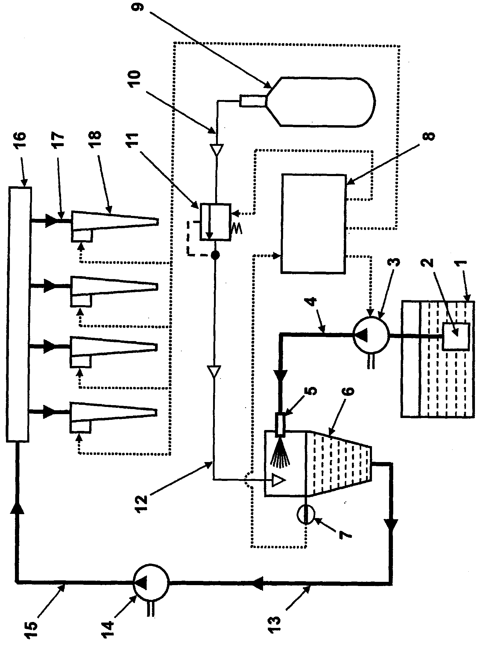
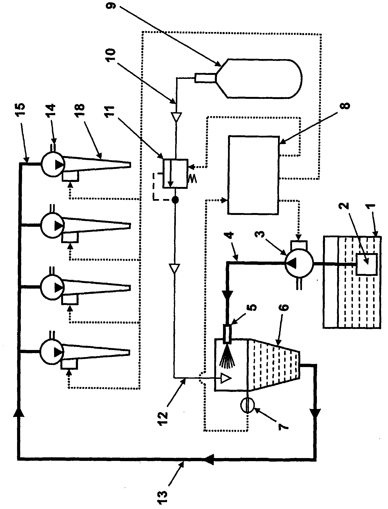
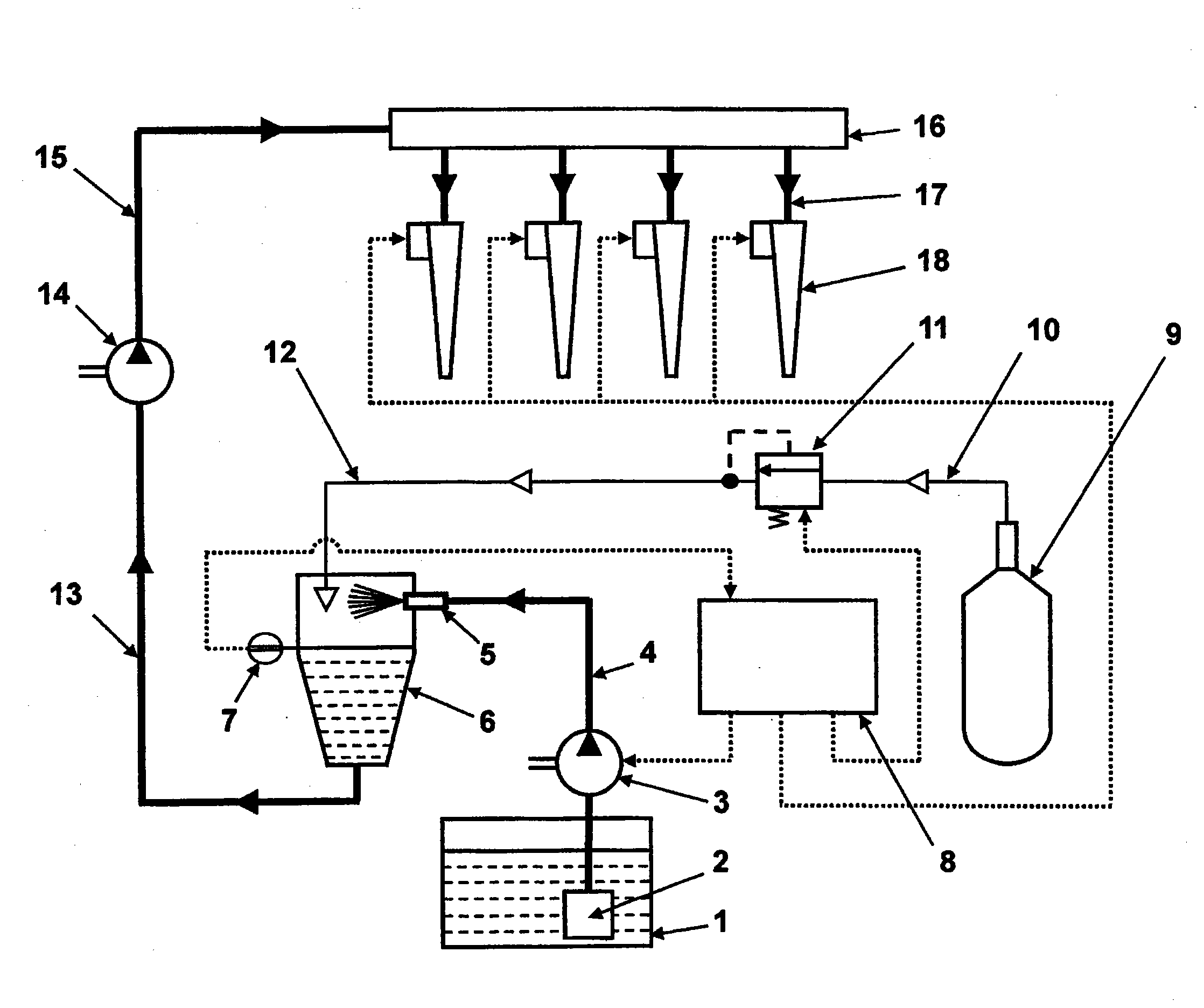
[0043] Referring now in detail to the attached figure 1 , the system consists of a fuel tank 1, a fuel filter 2, a low-pressure fuel pump 3 for delivering liquid fuel from the fuel tank 1 through a fuel line 4 to at least one diffuser nozzle 5 mounted in a fuel conditioning container 6 . Low-pressure fuel pump 3 provides fuel pressure P 1 . The level of fuel in the fuel regulating container 6 is controlled by a sensor 7 . Compressed gas 9 (e.g. air, CO 2 , oxygen, gas mixture, etc.) is jet-fluidically connected to the inlet of the pressure reducer 11 through the line 10, and the pressure reducer 11 controls the gas pressure downstream of the pressure reducer 11 in the line 12 at the level P 2 .

[0044] Pressure P 2 set to be lower than the fuel pressure P established by the low pressure fuel pump 3 at a level that provides satisfactory operating conditions for the nozzles 5 1 . Diffusion of the fuel in the gas achieves a sufficient amount of gas dissolved in the fuel....


PUM


Abstract

A fuel conditioning method is applicable to common rail direct injection or unit injector system. A liquid fuel is conditioned for higher-efficiency combustion in a combustion chamber. The conditioning system includes a fuel vessel (6) for fuel conditioning, at least one fuel dispersing nozzle (5) mounted for discharge into the fuel conditioning vessel (6), at least one gas inlet port (12), and at least one conditioned fuel outlet port (13) located in the vessel. A gas source (9) feeds a gas to the fuel conditioning vessel (6), wherein the gas is dissolved in the liquid fuel for forming a liquid/gas fuel solution. A low-pressure fuel pump (3) and a liquid fuel supply line (4) deliver liquid fuel from a fuel tank (1) to the at least one dispersing nozzle (5) of the fuel vessel (6) at pressure P1 higher than the gas pressure P2. A high-pressure fuel pump (14) feeds the liquid fuel/gas solution into a common rail (16) and further into fuel injectors (18), providing a pressure P4 higher than a pressure P5 in the combustion chamber at a moment of combustion.

Description

technical field [0001] The present invention relates to the field of liquid fuel combustion, and more particularly to a common rail fuel direct injection system or a unit injector system that supplies conditioned fuel in the form of an unsaturated solution to a high pressure fuel pump, said The fuel contains for example CO 2 or air or a gas mixture, with the aim of achieving a high degree of diffusion of the fuel in the combustion chamber of a reciprocating engine or gas turbine engine, or any other device having a combustion chamber. Background technique [0002] It is well known that diffusion of liquid fuel results in a substantial expansion of the effective surface of the liquid fuel, enabling the fuel to burn more efficiently. For example, the small size of the combustion chamber in a reciprocating engine results in partial deposition of the injected fuel on the piston, the combustion chamber walls creating a liquid film on the piston. This part of the fuel cannot be ...

Claims


Application Information

Patent Timeline
Patent Type & Authority Applications(China)
IPC IPC(8): F02M25/00F02M17/22
CPCF02M31/186Y02T10/126F02D19/12F02M25/10Y02T10/121F02M29/04F02M37/0064F02M25/00Y02T10/12
Inventor 伊戈尔·盖切克勒夫·古拉耶维克托·古林尤里·勒温瑙姆·斯塔罗塞尔斯基瑟曼·瓦伊恩贝拉特
Owner 极限燃烧公司
Why Eureka
Try Eureka