Capacitor module

A technology of capacitors and capacitor units, applied in capacitors, electrolytic capacitors, double-layer capacitors, etc., can solve the problems of reduced degree of freedom in flow path design, strength problems, etc., and achieve the effect of reducing constraints and improving strength

Inactive Publication Date: 2011-02-23
KOMATSU LTD
View PDF1 Cites 23 Cited by
  • Summary
  • Abstract
  • Description
  • Claims
  • Application Information

AI Technical Summary

Problems solved by technology

[0006] However, in the prior art described in the above-mentioned Patent Document 1, since the capacitor unit is screwed from the bottom surface side of the heat sink when the capacitor unit and the heat sink are connected, it is necessary to form the same number of capacitor units on the heat sink. Corresponding through-holes, which may cause problems in the overall strength of the module including the heat sink
In addition, since the flow path must be provided avoiding the many through-holes for fixing the capacitor unit, the degree of freedom in flow path design is reduced

Method used


Image

  • Capacitor module
  • Capacitor module
  • Capacitor module

Examples


Embodiment Construction

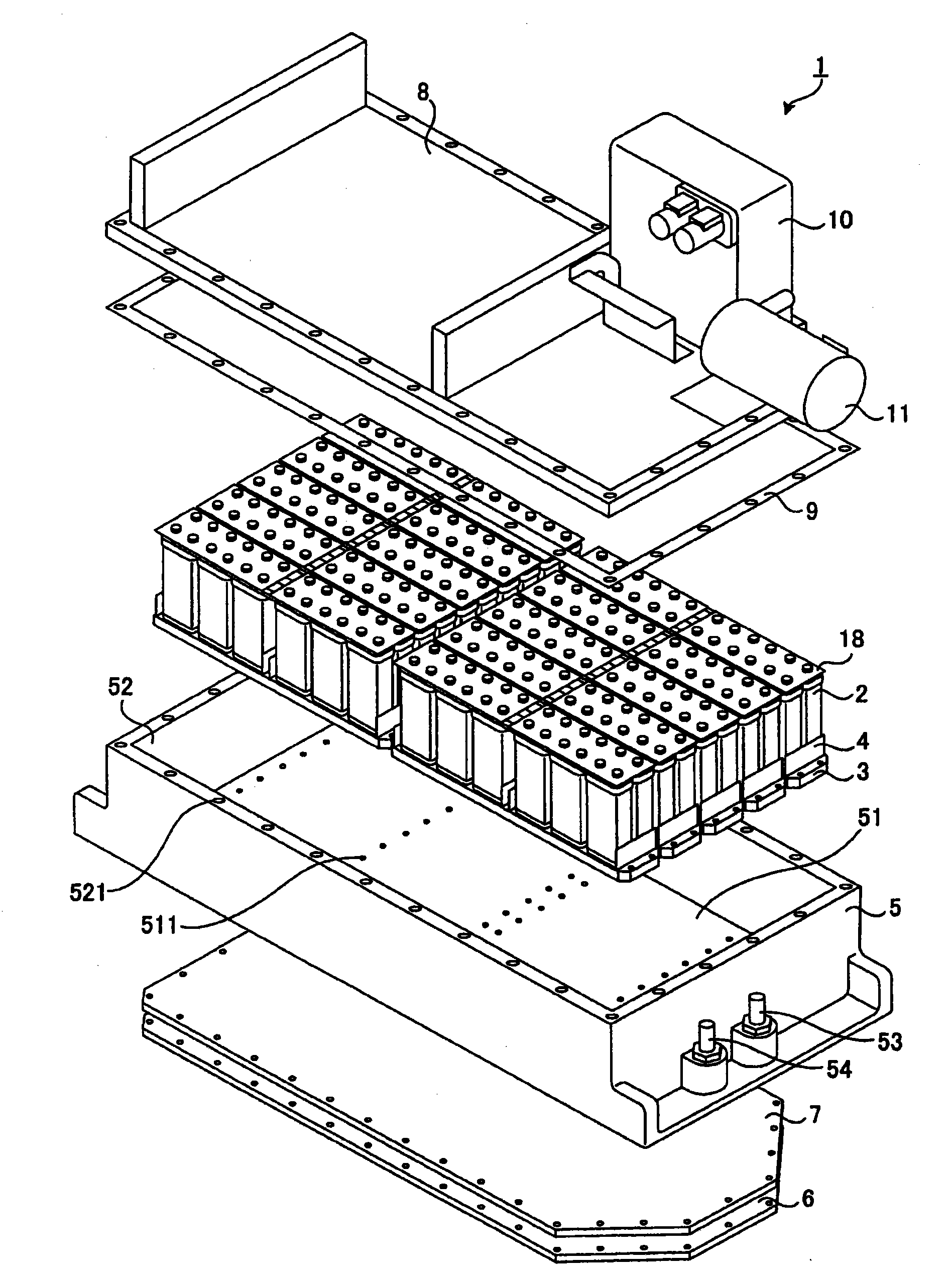
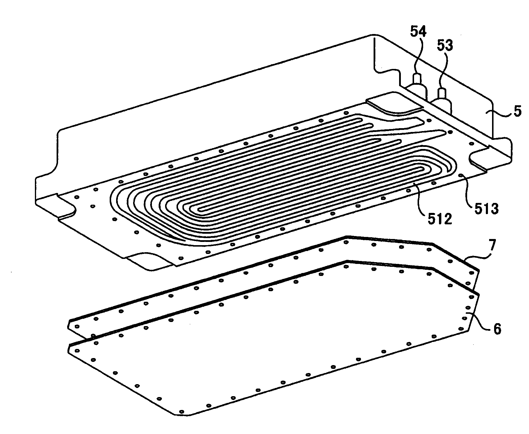
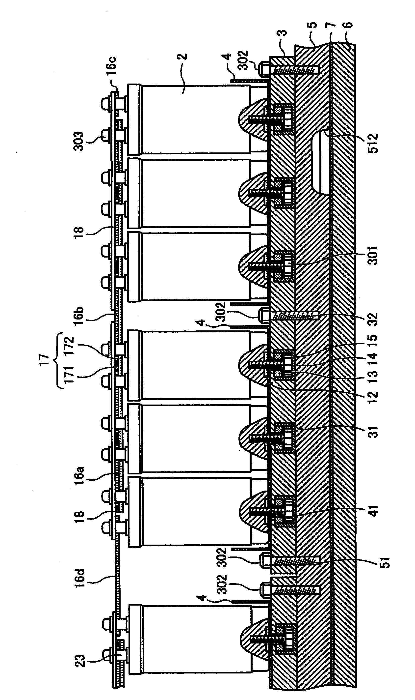
[0073] Hereinafter, preferred modes for implementing the present invention (hereinafter referred to as "embodiments") will be described with reference to the drawings. It should be noted that the drawings referred to in the following description are schematic diagrams, and when the same object is shown by different drawings, there may be differences in dimensions, scales, and the like.

[0074] figure 1 It is an exploded perspective view showing the structure of a capacitor module according to an embodiment of the present invention. figure 2 It is a figure which shows the schematic structure of the bottom part of the housing of the capacitor module of this embodiment. image 3 It is a partial cross-sectional view of the main part of the capacitor module seen in a cross section parallel to the longitudinal direction of the capacitor module of the present embodiment. Figure 4 It is a partial cross-sectional view of the main part of the capacitor module seen in a cross section ...


PUM


Abstract

A capacitor module having increased strength as a whole and having increased freedom in design of a cooling medium flow passage to be formed in the module. The capacitor module is provided with capacitor cells each having a capacitor and a capacitor case which is equipped with first closed-bottomed screw holes having respective openings in the bottom surface of the capacitor case and which houses the capacitor, a metallic cell-fixing body having through-holes communicating with the first screw holes and to which the capacitor cells are fixed by engaging cell screws into the through-holes and the first screw holes, an insulator consisting of a thermally conductive insulating material, installed between the cell-fixing body and the capacitor cells and, and insulating between the cell-fixing body and the capacitor cells, and a metallic heat-dissipating body having second closed-bottomed screw holes into which screws for the cell-fixing body are engaged and also having a flow passage for causing the cooling medium to flow to the rear side of that surface of the heat-dissipating body in which the second screw holes are formed.

Description

technical field [0001] The present invention relates to a capacitor module including a plurality of capacitor units each housing a capacitor. Background technique [0002] A hybrid vehicle equipped with an engine and a generator-motor as drive sources includes a power storage device that stores electric power generated by the generator-motor driven by the engine. The power storage device also functions as a power source for supplying electric power to the generator motor. As such an electric storage device, a capacitor module including a large-capacity capacitor is sometimes used. [0003] When a capacitor module is used as an electrical storage device of a hybrid construction machine, which is an example of a hybrid vehicle, since the construction machine frequently repeats driving and deceleration in units of several seconds to tens of seconds, the power applied to the capacitor If the load fluctuates greatly, the heat generated by the capacitor tends to increase. There...

Claims


Application Information

Patent Timeline
Patent Type & Authority Applications(China)
IPC IPC(8): H01G9/26H01G9/00
CPCY02T10/6217H01G2/08Y02T10/7022B60K6/46H01G9/155Y02E60/13B60Y2200/25B60Y2200/412H01G9/0003B60K6/28H01G2/04Y02T10/62Y02T10/70H01G11/10H01G11/18H01G11/82
Inventor 宗田昭彦
Owner KOMATSU LTD
Why Eureka
Try Eureka