
Automatic cleaning device for inner hole of cylinder cover

An automatic cleaning and cleaning device technology, applied in the direction of engine components, machines/engines, cleaning methods and appliances, etc., can solve the problems of low cleanliness, effort, and splashing of cleaning fluid in the cylinder head hole, and is suitable for mass production Effect

Inactive Publication Date: 2011-03-02
潍坊浩泰机械有限责任公司
View PDF5 Cites 20 Cited by
  • Summary
  • Abstract
  • Description
  • Claims
  • Application Information

AI Technical Summary

Problems solved by technology

[0002] Before the internal combustion engine is installed, all parts need to be cleaned; and the cylinder head of the internal combustion engine is time-consuming, laborious, and the cleaning effect is not good due to factors such as the large number of inner holes, large depth, and complex shape.
Most of the traditional methods are to set the cleaning nozzle at a certain distance from the orifice, and spray the cleaning liquid directly into the hole. During the cleaning process, a large amount of cleaning liquid fails to enter the hole, resulting in additional consumption; Under the resistance of the wall, the momentum is also rapidly lost, the cleaning ability is poor, the cleanliness in the cylinder head hole is low, and the cleaning efficiency is difficult to improve; moreover, this method causes the cleaning liquid to splash around, which brings difficulties to the protection, and the cleaning fluid flows everywhere. The cleaning fluid is also difficult to recycle, causing a lot of inconvenience
Traditional cleaning methods are not suitable for mass production

Method used


Image

  • Automatic cleaning device for inner hole of cylinder cover
  • Automatic cleaning device for inner hole of cylinder cover

Examples


Embodiment Construction

[0015] The present invention will be further described below with reference to the accompanying drawings and embodiments. In the following detailed description, certain exemplary embodiments of the present invention have been described by way of illustration only. Needless to say, as those skilled in the art would realize, the described embodiments may be modified in various different ways, all without departing from the spirit and scope of the present invention. Accordingly, the drawings and description are illustrative in nature and are not intended to limit the scope of protection of the claims.

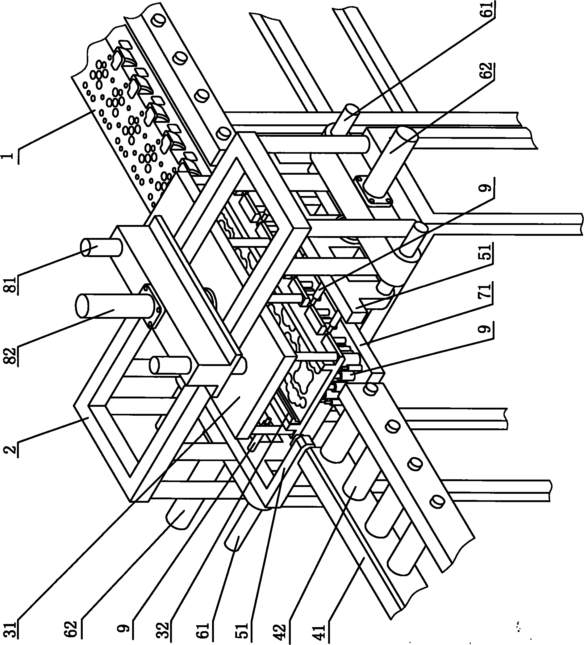
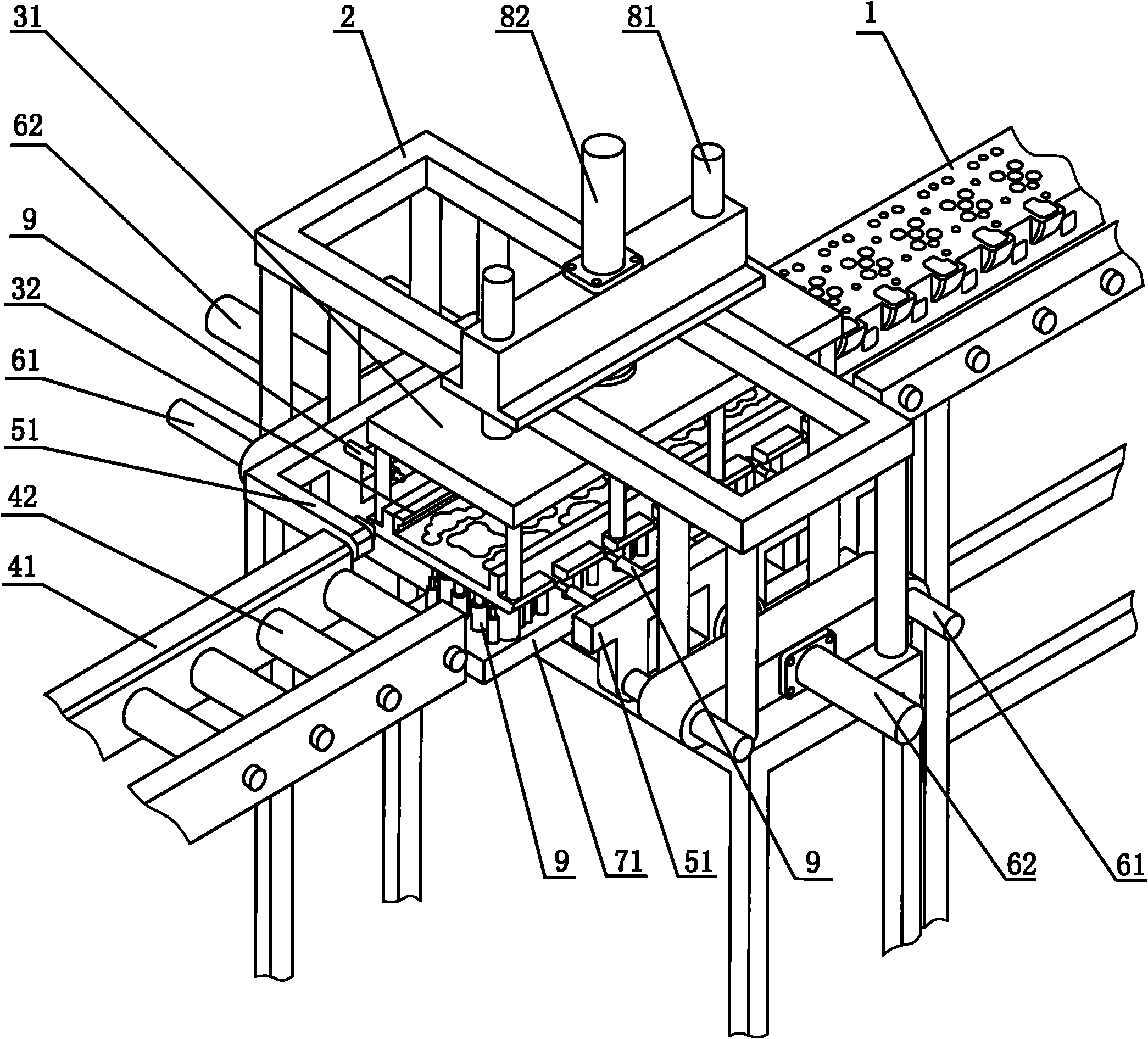
[0016] As shown in the drawings, the automatic cleaning device for the inner hole of the cylinder head, used for cleaning the inner hole of the cylinder head 1, includes a frame 2, and a cylinder head cleaning bracket 31 is installed on the frame 2, and the cylinder head cleaning bracket The rack 31 is provided with a cylinder head inlet end and a cylinder head outlet end, and th...


PUM


Abstract

The invention discloses an automatic cleaning device for an inner hole of a cylinder cover, which is used for cleaning the inner hole of the cylinder cover. The automatic cleaning device comprises a rack; a cylinder cover cleaning bracket is arranged on the rack; the cylinder cover cleaning bracket is provided with a cylinder cover feeding end and a cylinder cover discharge end; the cylinder cover feeding end and the cylinder cover discharge end are connected with a cylinder cover conveying device respectively; at least one telescopic cleaning device capable of extending to the inner hole of the cylinder cover for cleaning is arranged on the rack; and a telescopic driving device is arranged between the telescopic cleaning device and the rack. The cylinder cover enters the cylinder cover cleaning bracket through the cylinder cover conveying device, and the spray head part of each cleaning device enters the inner hole of the cylinder cover to perform spraying and cleaning, so the cleaning time is short and the cleaning efficiency is high; the cleaning solution is directly sprayed onto the hole wall in the inner hole of the cylinder cover, so the pressure loss of the cleaning solution is extremely low, and the cleaning effect is good; and the whole cleaning process does not need manual operation and has high automation degree. The automatic cleaning device has the advantages of high automation degree, good cleaning effect, high cleaning efficiency and suitability for large-batch production.

Description

technical field [0001] The invention relates to an automatic cleaning device for cleaning the cylinder head of an internal combustion engine. Background technique [0002] Before the internal combustion engine is installed, all parts need to be cleaned; while the cylinder head of the internal combustion engine is time-consuming and laborious with traditional cleaning methods due to the large number of inner holes, large depth and complex shape, and the cleaning effect is not good. Most of the traditional methods are to set the cleaning nozzle at a certain distance from the orifice, and spray the cleaning liquid directly into the hole. During the cleaning process, a large amount of cleaning liquid fails to enter the hole, resulting in additional consumption; the cleaning liquid entering the hole is in the hole. Under the resistance of the wall, the impulse is also rapidly lost, the cleaning ability is poor, the cleanliness in the cylinder head hole is low, and the cleaning ef...

Claims


Application Information

Patent Timeline
IPC IPC(8): F02B77/04B08B3/02
Inventor 蒲光明
Owner 潍坊浩泰机械有限责任公司
Learn More