Lens unit, camera module and lens unit manufacturing method

A lens unit, lens technology, applied in optical components, instruments, installations, etc., can solve problems such as inability, and achieve the effect of simple structure

Inactive Publication Date: 2011-03-02
MAXELL HLDG LTD
View PDF4 Cites 20 Cited by
  • Summary
  • Abstract
  • Description
  • Claims
  • Application Information

AI Technical Summary

Problems solved by technology

[0010] However, in the case of such alignment, it takes a long time to stack the lenses, and the alignment cannot be easily performed.

Method used


Image

  • Lens unit, camera module and lens unit manufacturing method
  • Lens unit, camera module and lens unit manufacturing method
  • Lens unit, camera module and lens unit manufacturing method

Examples


no. 1 approach

[0074] Below, refer to figure 1 A first embodiment of the present invention will be described through FIG. 9 .

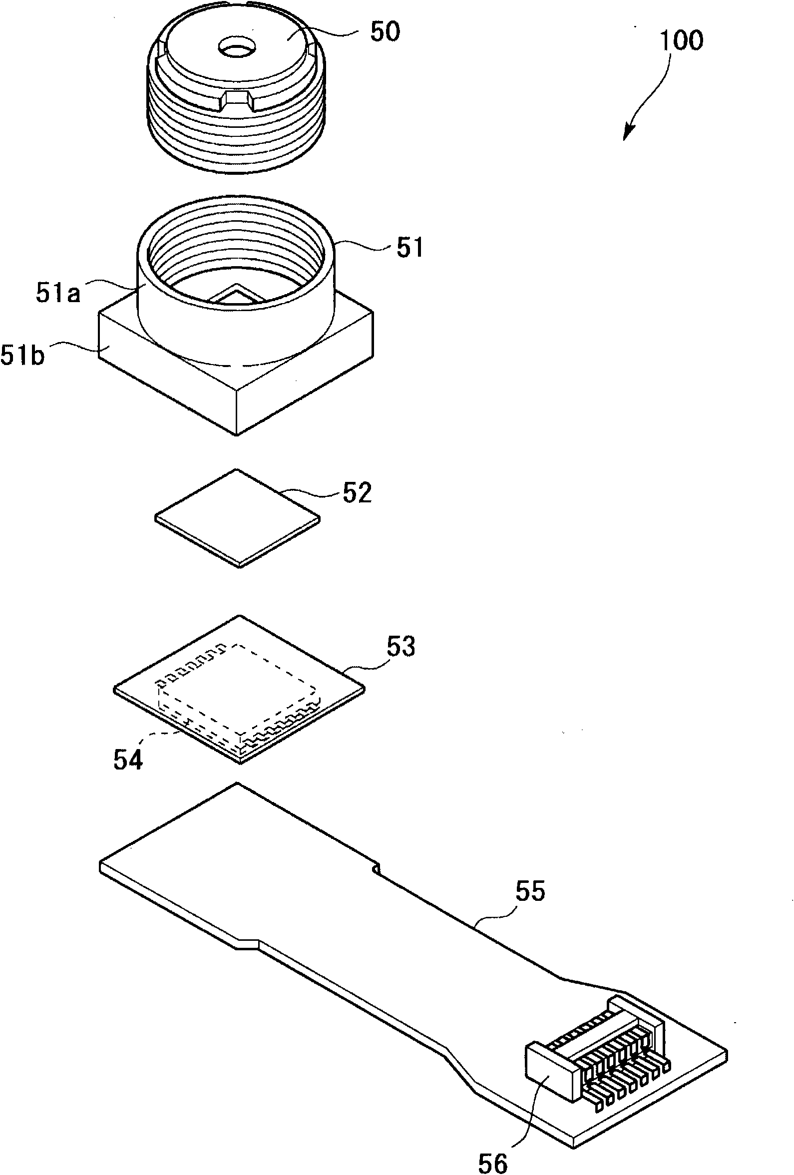
[0075] First, refer to figure 1 , to describe the structure and function of the camera module. like figure 1 As shown, the camera unit 100 has a lens unit 50 , a mount 51 , an imaging element 52 , a wiring board 53 , a signal processing circuit 54 , flexible wiring 55 , and a connector 56 .

[0076] The camera module 100 is assembled in a small electronic device such as a mobile phone or a notebook computer. The camera module 100 outputs the image formed by the imaging element 52 as an electrical signal through the connector 56 .

[0077] The lens unit 50 is an optical component that mounts a lens in a lens barrel. A screw groove is formed on the outer peripheral surface of the lens unit 50 .

[0078] The seat 51 is a base member on which the lens unit 50 is mounted. The seat 51 has a cylindrical portion 51a and a base portion 51b. A screw groove is formed i...

no. 2 approach

[0139] Below, refer to Figure 10A and Figure 10B , the second embodiment of the present invention will be described.

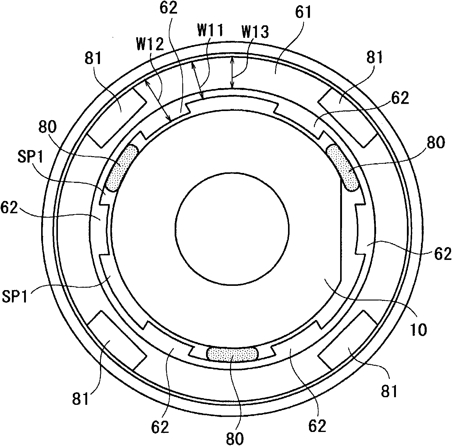
[0140] In this embodiment, unlike the first embodiment, the number of convex portions 62 is different. Also in this case, the same effect as that of the first embodiment can be obtained.

[0141] Figure 10A In the case shown, the barrel portion 60 has four protrusions 62 . Figure 10B In the case shown, the barrel portion 60 has three protrusions 62 . In either case, the same effect as that of the first embodiment can be obtained. In addition, by increasing the number of convex portions 62 , the lens 10 can be firmly fixed to the cylindrical portion 60 .

no. 3 approach

[0143] Below, refer to Figures 11A to 15D A third embodiment of the present invention will be described.

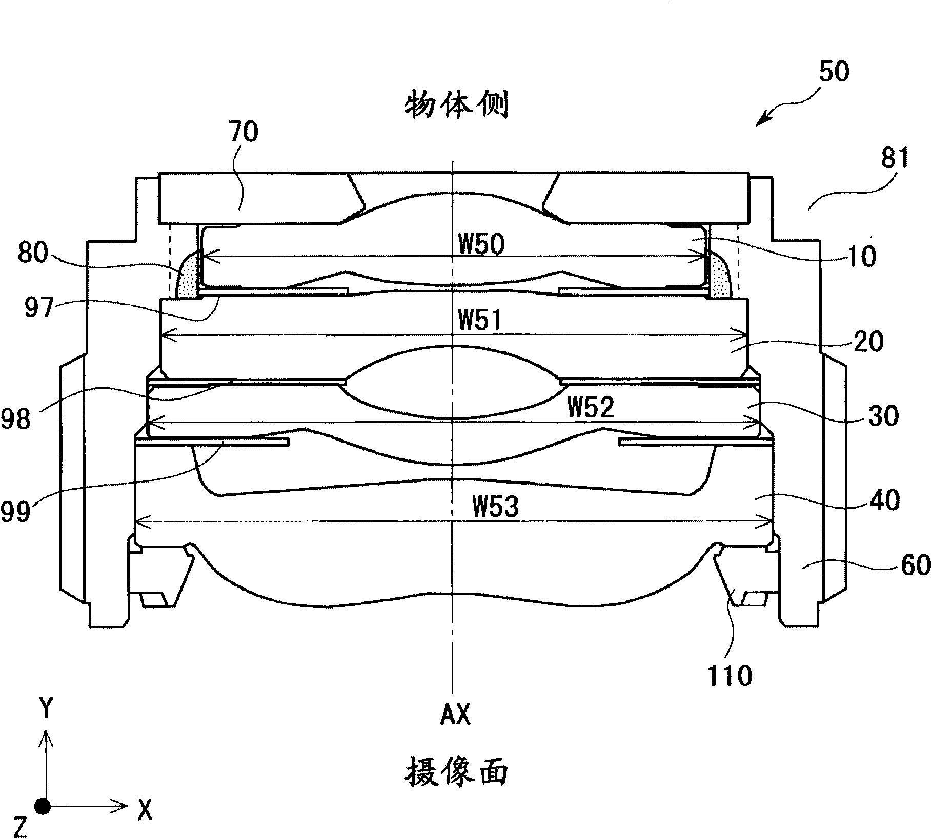
[0144] refer to Figures 11A to 14B The configuration of the lens unit 50 will be described. in addition, Figure 11A express with Figure 11B The end faces shown are different from the end faces.

[0145] like Figure 11A and Figure 11B As shown, the lens unit 50 has a lens 10 , a lens 20 , a lens 30 , a lens 40 , a cylinder portion (holding body) 60 , a cover portion (cover body) 70 , a light shielding sheet 98 , a light shielding sheet 99 , and a pressing member 110 . The lens unit 50 emits a light beam incident from the front (object side) to the rear (imaging element side) through a plurality of lenses.

[0146] The lenses 10 to 40 form an image of the light beam incident from the object side on the imaging plane of the imaging element 52 . Each of the lenses 10 to 40 has a lens portion and a flange portion. The lens portion is a portion that functions opt...


PUM


Abstract

Lens alignment is performed by a simple constitution or an easy method. A lens unit (50) is provided with a plurality of lenses (10-40) each of which has a lens section and a flange section surrounding the lens section; and a holding body (60) which holds the lenses (10-40) sequentially arranged along an optical axis. The holding body (60) has first and second receiving sections sequentially formed along the optical axis. The first receiving section presses a flange section side surface along the optical axis and holds the lenses (20-40), and the second receiving section receives the lens (10) in a state where the second receiving section can be moved in a direction intersecting with the optical axis.

Description

technical field [0001] The invention relates to a lens unit, a camera assembly and a method for producing the lens unit. Background technique [0002] In recent years, it has been common to assemble camera modules on various electronic devices such as mobile phones and notebook computers. It is possible to achieve higher added value of electronic equipment by incorporating a camera module in electronic equipment and adding an imaging function to electronic equipment. [0003] In such a camera module, there are various development goals such as performance improvement, miniaturization, and price reduction. [0004] For example, Patent Document 1 discloses a technology for downsizing a lens unit included in a camera module. In Patent Document 1, recesses formed on both the lens and the lens barrel are connected to each other to form a holding groove for an adhesive for bonding the lens and the lens barrel. Thereby, it is possible to eliminate the provision of other componen...

Claims


Application Information

Patent Timeline
Patent Type & Authority Applications(China)
IPC IPC(8): G02B7/02
CPCG02B7/025G02B7/023G02B7/021
Inventor 平田弘之荒井治夫桥本昌俊铃木雅博
Owner MAXELL HLDG LTD
Why Eureka
Try Eureka