Check patentability & draft patents in minutes with Patsnap Eureka AI!

Method for driving active matrix organic light-emitting diode (LED) display panel

A light-emitting diode and active matrix technology, which is applied to cathode ray tube indicators, static indicators, instruments, etc., can solve the problems of poor luminous efficiency, aging of finished product efficiency, and increased power consumption of active matrix organic light-emitting diode displays. , to achieve the effect of increasing luminous efficiency and reducing power consumption

Active Publication Date: 2011-03-09
AU OPTRONICS CORP
View PDF6 Cites 45 Cited by
  • Summary
  • Abstract
  • Description
  • Claims
  • Application Information

AI Technical Summary

Problems solved by technology

[0003] However, due to the poor luminous efficiency of the blue material (B2) in the current active matrix OLED display panel (OLED display panel), the OLED driving circuit / device (that is, driving the thin film transistor (driver TFT)) must provide a relatively large driving current to enable it to exhibit a considerable luminous ability, but relatively shorten the service life of the blue material, and cause the overall power consumption of the active matrix organic light emitting diode display (power consumption) increases, so that the finished product of the active matrix organic light emitting diode display has the problem of efficiency aging

Method used


Image

  • Method for driving active matrix organic light-emitting diode (LED) display panel
  • Method for driving active matrix organic light-emitting diode (LED) display panel
  • Method for driving active matrix organic light-emitting diode (LED) display panel

Examples


Embodiment Construction

[0032] Reference will now be made in detail to embodiments of the invention, examples of which are illustrated in the accompanying drawings. In addition, wherever possible, elements / components using the same reference numerals in the drawings and embodiments represent the same or similar parts.

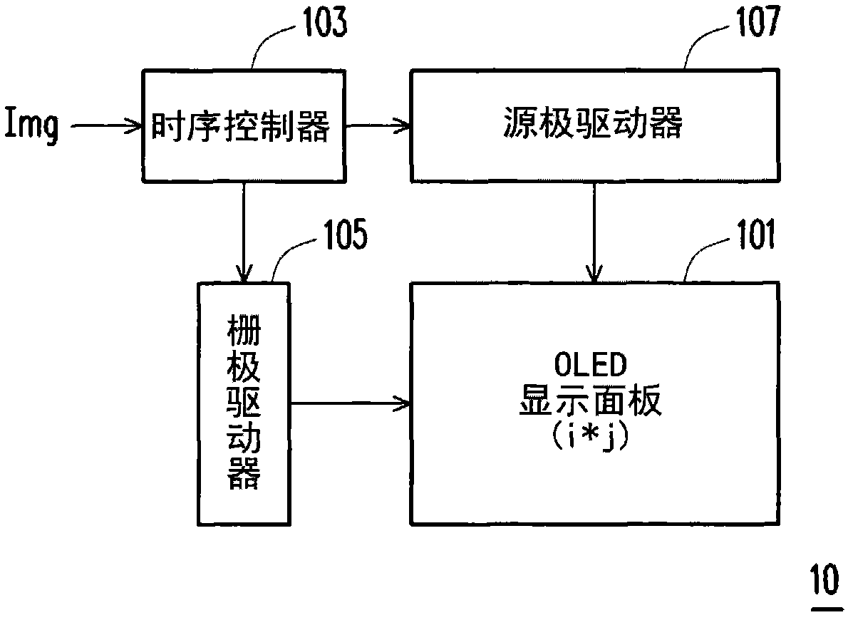
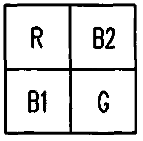
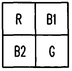
[0033] figure 1 A system block diagram of an active matrix organic light emitting diode display (AMOLED display) 10 according to an embodiment of the present invention is shown. Please refer to figure 1 , the active matrix organic light emitting diode display 10 may include an active matrix organic light emitting diode display panel (AMOLED display panel) 101, a timing controller (timing controller, T-con) 103, a gate driver (gate driver) 105, and a source pole driver (source driver) 107 . Wherein, the OLED display panel 101 has a plurality of pixels (pixels) arranged in an array (i*j), and each pixel has red, green, first blue (light blue) and second blue (dark blue) Four sub-pix...


PUM


Abstract

The invention discloses a method for driving an active matrix organic light-emitting diode (LED) display panel, which is characterized in that an operational method is effectively designed by using the characteristics of the (1931) CIE color gamut coordinate and the operational method is used for deciding how to drive a single pixel with red, green, a first blue (light blue) and a second blue (dark blue) sub-pixels. Moreover, only one sub-pixel of the light blue and dark blue sub-pixels in the single pixel can be subject to color mixture with other red and green sub-pixels at the same time. Thus, not only the luminous efficiency of an active matrix organic LED can be increased, but also the whole power consumption of an active matrix organic LED display can be reduced.

Description

technical field [0001] The invention relates to a plane display technology, and in particular to a driving method of an active matrix organic light emitting diode display panel. Background technique [0002] Due to the rapid progress of the multimedia society, the technologies of semiconductor devices and display devices have also undergone rapid progress. As far as the display is concerned, since the active matrix organic light emitting diode (AMOLED) display has no viewing angle limitation, low manufacturing cost, high response speed (about a hundred times higher than that of liquid crystal), power saving, self-illumination, It can be used for DC drive of portable machines, has a wide operating temperature range, is light in weight, and can be miniaturized and thinned along with hardware devices to meet the characteristic requirements of displays in the multimedia era. Therefore, the active matrix organic light emitting diode display has great potential for development, a...

Claims


Application Information

Patent Timeline
IPC IPC(8): G09G3/32G09G5/02G09G3/3225
Inventor 杨学炎蔡子健
Owner AU OPTRONICS CORP
Features
  • R&D
  • Intellectual Property
  • Life Sciences
  • Materials
  • Tech Scout
  • Unparalleled Data Quality
  • Higher Quality Content
  • 60% Fewer Hallucinations
Learn More