Eureka AIR delivers breakthrough ideas for toughest innovation challenges, trusted by R&D personnel around the world.

Method, system and device for building trans-regional flow engineering tunnel

A technology of traffic engineering and tunnel establishment, which is applied in the field of communication, and can solve problems such as inability to automatically configure intermediate nodes of TE tunnels, slow establishment of TE tunnels, and large investment in human resources.

Inactive Publication Date: 2011-03-09
BEIJING XINWANG RUIJIE NETWORK TECH CO LTD
View PDF4 Cites 9 Cited by
  • Summary
  • Abstract
  • Description
  • Claims
  • Application Information

AI Technical Summary

Problems solved by technology

[0048] Embodiments of the present invention provide a method, system, and device for establishing a cross-regional traffic engineering tunnel, which are used to solve the problem of intermediate nodes that cannot be automatically configured for TE tunnels in the prior art, slow establishment of TE tunnels, long delays, and human resources. The problem of investing too much

Method used


Image

  • Method, system and device for building trans-regional flow engineering tunnel
  • Method, system and device for building trans-regional flow engineering tunnel
  • Method, system and device for building trans-regional flow engineering tunnel

Examples


Embodiment 1

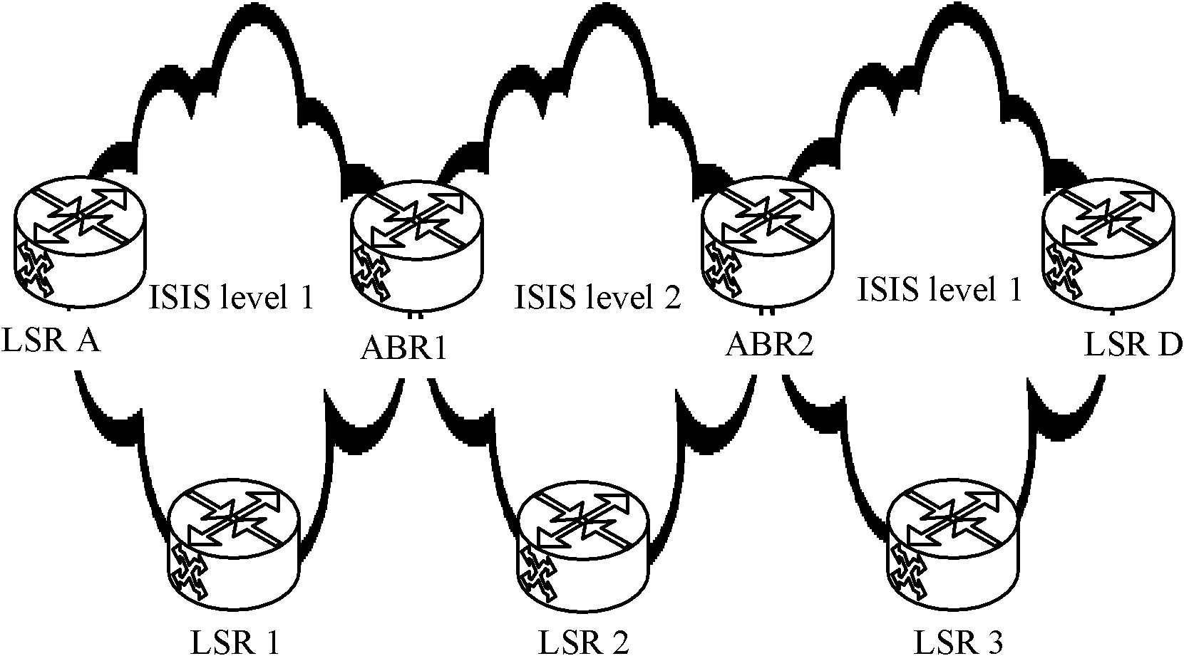
[0151] The method for establishing a cross-regional traffic engineering tunnel provided by Embodiment 1 of the present invention is aimed at realizing the establishment of a cross-regional TE tunnel for the MPLS system architecture using the ISIS protocol. The structure example of the system is as follows Figure 6 As shown, the system includes: three non-backbone areas level1 and one backbone area level2, and several routing devices, which may be label switching routers LSR.

[0152] Specifically Figure 6 The backbone area, the first non-backbone area, the second non-backbone area, and the third non-backbone area shown in , and the LSRA and LSR 1 that belong only to the first non-backbone area, and the LSRD and LSR that only belong to the second backbone area LSR 2, LSR 3 belonging only to the third non-backbone area, ABR1 belonging to the backbone area and the first non-backbone area, ABR2 belonging to the backbone area and the second non-backbone area, and ABR belonging to...

Embodiment 2

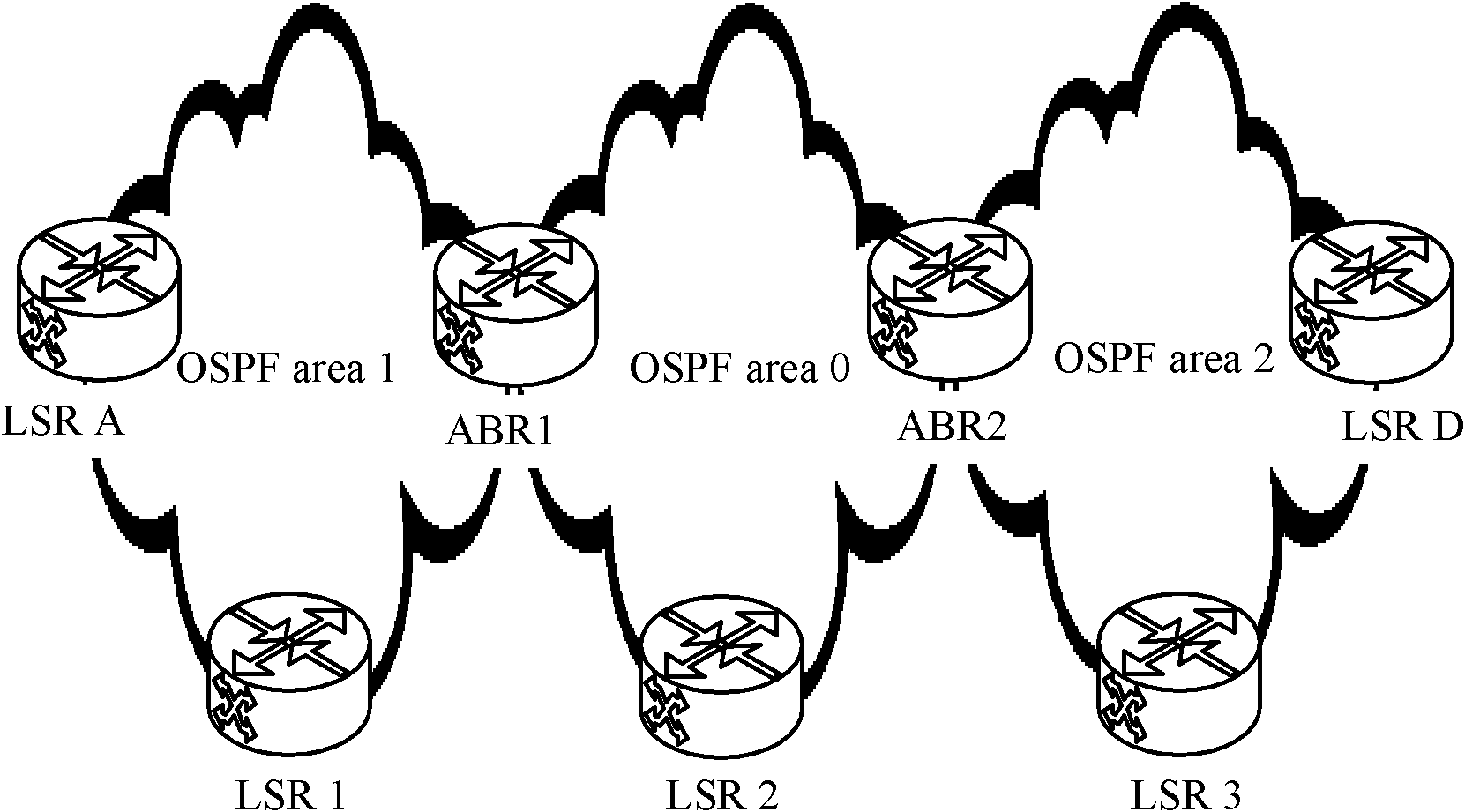
[0202] The method for establishing a cross-regional traffic engineering tunnel provided by Embodiment 2 of the present invention is aimed at realizing the establishment of a cross-regional TE tunnel for the MPLS system architecture using the OSPF protocol. The structure example of the system is as follows Figure 8 As shown, the system includes: one backbone area, three non-backbone areas, and several routing devices, which may be label switching routers LSR.

[0203] Specifically Figure 8 The backbone area (area0), non-backbone area (area1, area2, area3) shown in , and LSRA and LSR 1 only in area1, LSRD and LSR 2 only in area2, and only in area3 LSR 3, and ABR1 belonging to area0 and area1, ABR2 belonging to area0 and area2, and ABR3 belonging to area0 and area3. Of course, in the actual network deployment, the non-backbone areas are not limited to three and can be set arbitrarily, as long as each non-backbone area is directly or indirectly connected to the backbone area ar...


PUM


Abstract

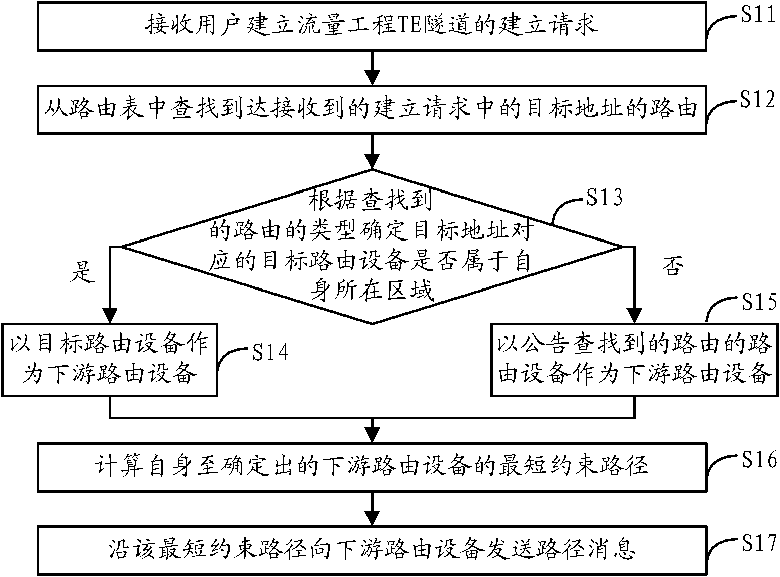
The invention discloses a method, a system and a device for building a trans-regional flow engineering tunnel, wherein the method comprises the following steps: when a building request is received, or a path message sent by an upstream routing device is received and a destination address carried in the path message is not the address of the path message, looking up a route for arriving at the destination address; determining whether a target routing device belongs to the region in which the target routing device is located according to the type of the route, thereby determining a downstream routing device; calculating the shortest constraint path from the target route device to the downstream routing device, then sending the path message to the downstream routing device; when the target address carried in the path message is the address of the path message, returning a resource reserve message; when receiving the resource reserve message returned by the downstream routing device, sending the received resource reserve message to the upstream routing device or confirming the completion of the building of the TE tunnel. The method, the system and the device of the invention have the advantages of realizing that a trans-regional flow engineering tunnel is built without manually configuring necessarily-passed nodes by users, improving the speed and efficiency of tunnel building, and reducing the inputs of human resource.

Description

technical field [0001] The present invention relates to the field of communication technology, in particular to a cross-area traffic engineering (Traffic Engineering, TE) tunnel establishment method, system and device related to a multi-protocol label switching (Multi Protocol Label Switch, MPLS) system. Background technique [0002] MPLS traffic engineering is a technical solution to manage and control user business data traffic, and map data traffic to physical topology / links. An existing MPLS network system may use an Intermediate System to Intermediate System (Intermediate System to Intermediate System, ISIS) protocol or an Open Shortest Path First (Open shortest path first, OSPF) protocol as a routing protocol. [0003] Among them, such as figure 1 Shown is an example of a system architecture using the ISIS protocol. Including: backbone area (ISIS level2), two non-backbone areas (ISIS level1) and several label switching routers (LabelSwitch Router, LSR); for example: ...

Claims


Application Information

Patent Timeline
Patent Type & Authority Applications(China)
IPC IPC(8): H04L12/56H04L12/46H04L45/74
Inventor 刘金辉
Owner BEIJING XINWANG RUIJIE NETWORK TECH CO LTD
Why Eureka
Eureka Blog
Learn More