Pulper with torque motor

A pulper and electric motor technology, applied to mixers with rotating stirring devices, mixers, mixer accessories, etc., can solve the problems of serious cost maintenance, increase the floor area of ​​the pulper, etc., and achieve the goal of reducing damage risk effect

Active Publication Date: 2013-03-13
BTA INT +1
View PDF1 Cites 0 Cited by
  • Summary
  • Abstract
  • Description
  • Claims
  • Application Information

AI Technical Summary

Problems solved by technology

Even at low speeds, a double belt drive is required which, while achieving a very high rotor torque, requires corresponding dimensioning of the drive elements, which in addition to the disadvantage of increasing the footprint of the pulper In addition, it makes the problem very serious not only in terms of cost but also in terms of related maintenance

Method used


Image

  • Pulper with torque motor
  • Pulper with torque motor

Examples


Embodiment Construction

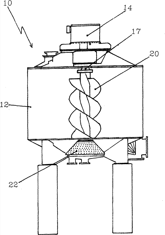
[0023] now refer to figure 1 , a pulper generally designated by reference numeral 10 is shown in the figure. The pulper rotor 20 is housed, centrally mounted, in a cylindrical pulper housing 12, the bottom of which adjoins a screen 22 which allows only sufficiently ground and dissolved material to pass through. The rotor 20 is powered by means of a three-phase synchronous motor whose motor housing 14 is centrally located on the top of the pulper housing 12 and connected by a flange 19 (see figure 2 ) to the pulper housing. The bottom of the pulper is connected to a discharge member for removing the pulper contents.

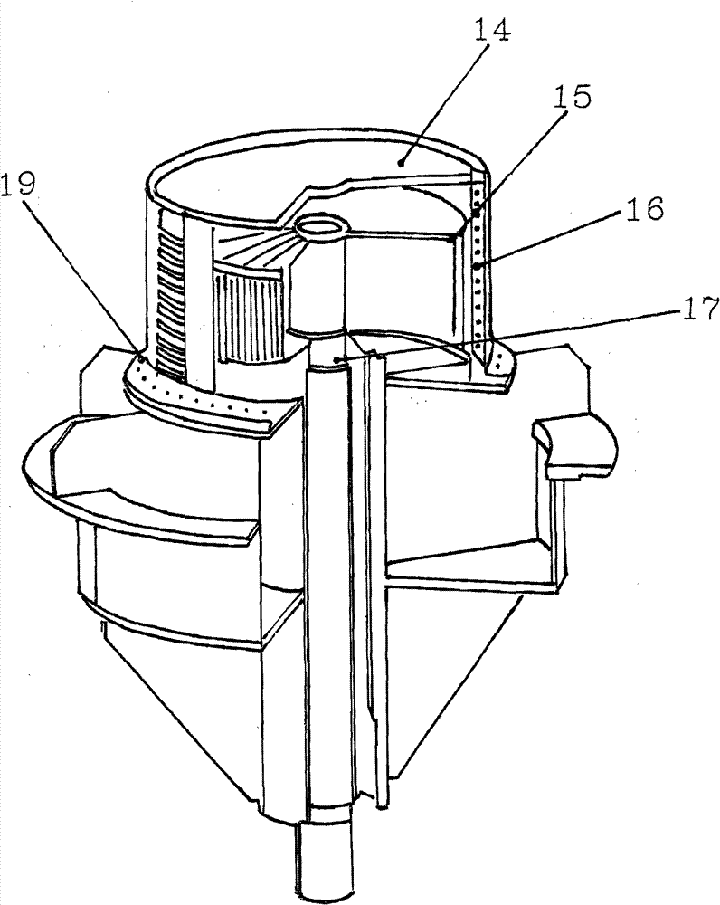
[0024] now refer to figure 2 , shows on an enlarged scale how the torque motor is flanged to the pulper housing by means of a flange 19 . The stator 16 and the rotor 15 of the motor can be seen in a section through the motor housing 14 . In the connecting portion 17 the motor output shaft is connected to the shaft of the pulper rotor.


PUM


Abstract

The pulper (10) has a rotor (20) provided in a container for defibering of material mixture. A filter (22) is utilized for removing the mixture from the container. The rotor is driven with an electrical motor, which comprises a drive shaft, which stands in connection with the rotor. The motor is designed as a three phase current-synchronous motor for operating at a rotary speed between zero and thousand revolution per minute. The synchronous motor is attached at an output of a frequency converter that is controlled by a control device. A drive shaft output is connected directly with the rotor. An independent claim is also included for a method for operating the pulper.

Description

technical field [0001] The invention relates to a pulper and its method of operation. Background technique [0002] The task of a pulper is to recover easily shredded paper stock mixtures, an important application especially in the recovery of waste products such as waste paper and similar waste products, including biowaste, by separating recyclable components from non-recyclable components. [0003] One such pulper generally comprises a casing containing a rotor in which the feed to be recovered is filled together with a liquid, usually water. The rotation of the rotor under power creates a strong flow force that defibrates the solids, separates themselves and shortens the detached fibers so that a part of them and other substances contained in the stock mixture go into solution. However, since in the present case this is mainly concerned with fiber separation, no particular attention has been paid to the concomitant size reduction and dissolution, but it should be underst...

Claims


Application Information

Patent Timeline
Patent Type & Authority Patents(China)
IPC IPC(8): D21B1/32
CPCD21B1/345Y02W30/64B02C19/22B02C23/36B07B1/20D21H17/01B02C2201/06Y02W30/91B01F27/92B01F35/20B01F2101/47
Inventor 哈里·维扬罗兰·卡拉斯特凡诺·博萨诺
Owner BTA INT
Why Eureka
Try Eureka