
Roller blind system for a motor vehicle

A technology that plays a role in automobiles, applied to vehicle parts, anti-glare equipment, roofs, etc., can solve problems such as the disadvantages of levers

Inactive Publication Date: 2011-03-30
BOS
View PDF9 Cites 1 Cited by
  • Summary
  • Abstract
  • Description
  • Claims
  • Application Information

AI Technical Summary

Problems solved by technology

However, the levers that make up the puller are disadvantageous from an aesthetic point of view
Although it is also known from the prior art to use lateral guide rails instead of the pull-out device for guiding the head parts for protection or shading systems, this is not possible in every installation situation, especially in the open state in the active state. is not possible when the wind deflector system

Method used


Image

  • Roller blind system for a motor vehicle
  • Roller blind system for a motor vehicle
  • Roller blind system for a motor vehicle

Examples


Embodiment Construction

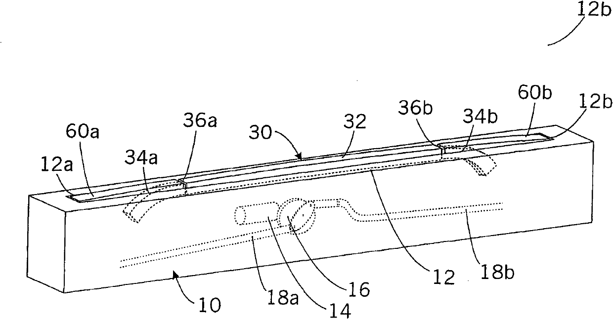
[0029] Figure 1a and 1b Shown is a protection or shading system according to the invention. Among them, in particular, the wind deflector system of a convertible car, which is arranged in the area behind the vehicle seats in order to reduce the Figure 1a The air vortex in the passenger range of the car when it is in effect.

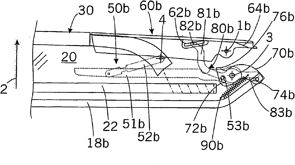
[0030] The system has a base 10 which is arranged in a stationary manner in the vehicle. On the upper side of the base 10 an outlet slit 12 is provided, through which a planar structure 20 such as a textile planar structure or a net can be pulled out of the base 10, on the distal end of which the planar structure is equipped with an end Header 30. Arranged inside the base 10 is the Figure 1a and 1b The reel 22, not shown, is used to accept the Figure 1b Surface structure 20 in rest state. Used to connect the planar structure 20 and the end part 30 from Figure 1b The static position moves to Figure 1a The mechanical energy required for the acti...


PUM


Abstract

The present invention relates to a protection or shading system for a motor vehicle, having a base (10), a sheet-like structure (20) entendable between an inoperative position and a functional position in an extension direction (2) away from the base, a rigid end element (30) fastened to the sheet-like structure, and an extension device (50b) fastened on one side to the base and on the other side to the end element. The extension device is designed so as to transfer the system from an inoperative state in which the sheet-like structure (20), the end element (30) and the extension device (50b) are each in an inoperative position, into a functional state, in which the sheet-like structure (20), the end element (30) and the extension device (50b) are each in a functional position. A covering panel (60b) is hinged to the base and can be deflexed to a first swinging position to abut against or at least partly around the extension device (50b) that is in the functional position.

Description

technical field [0001] The invention relates to a protection or shading system for a motor vehicle, in particular to a windshield system for a convertible motor vehicle. Background technique [0002] This type of protection-or shading system has a base with a surface structure that can be pulled out from the base in the direction of pull-out between a rest position and an active position, with a surface structure fixed on the surface structure. A rigid terminal part, which is arranged on the distal end of the planar body relative to the base, and has a pull-out device fixed on the one hand to the base and on the other hand to the terminal part. Among them, the pull-out device is designed to switch the system from the static state in which the planar structure, the end part and the pull-out device are in the rest position to the functioning state by mechanically loading the drive mechanism , in the functioning state the planar structure, the end piece and the puller are each...

Claims


Application Information

Patent Timeline
Patent Type & Authority Applications(China)
IPC IPC(8): B60J3/00
CPCB60J7/223B60J1/2013B60J3/002E06B9/24
Inventor M·埃伦贝格尔R·索尔
Owner BOS
Features
  • Generate Ideas
  • Intellectual Property
  • Life Sciences
  • Materials
  • Tech Scout
  • Unparalleled Data Quality
  • Higher Quality Content
  • 60% Fewer Hallucinations
Learn More