
Multi-gap discharge unit for ozone generator

A technology for ozone generators and discharge units, applied in the field of ozone generators, can solve the problems of high manufacturing difficulty, low ozone yield, and large number of discharge units, so as to reduce equipment investment and maintenance costs, and increase output and concentration , Ease of manufacture and installation

Inactive Publication Date: 2011-03-30
FUJIAN NEWLAND ENTECH CO LTD
View PDF7 Cites 3 Cited by
  • Summary
  • Abstract
  • Description
  • Claims
  • Application Information

AI Technical Summary

Problems solved by technology

However, in the existing discharge unit with multi-gap structure, there is no special limitation on the size of the two gaps, resulting in the discharge gap of the existing discharge unit being relatively large, and the relationship between the size of the two gaps is uncertain, which cannot be reasonably distributed. The amount of oxygen in the two gaps, so the ozone generator using this type of discharge unit produces a small amount of ozone, low concentration, low efficiency, and low ozone yield under the same amount of oxygen input. The large-capacity ozone generator covers a large area, contains a large number of discharge units, and the equipment cost is high, so the input-output ratio of the equipment is low, resulting in a reduction in the cost performance of the equipment
In addition, the high-voltage electrodes, insulating layers, and ground electrodes in the existing discharge unit are strictly required to be installed in concentric circles, which requires high installation requirements, difficult manufacturing, and high cost

Method used


Image

  • Multi-gap discharge unit for ozone generator
  • Multi-gap discharge unit for ozone generator
  • Multi-gap discharge unit for ozone generator

Examples


Embodiment 1

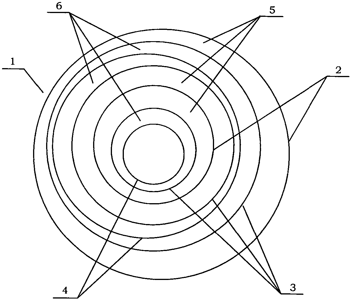
[0028] Such as figure 1 As shown, a multi-gap discharge unit 1 for an ozone generator provided by Embodiment 1 of the present invention includes a group of ring-shaped ground electrodes 2 , insulating layers 3 and high-voltage electrodes 4 installed layer by layer. In this embodiment, the number of high voltage electrodes 4 is 2, the number of insulating layers 3 is 3, and the number of ground electrodes 2 is 2. In practical applications, the numbers of ground electrodes 2, insulating layers 3 and high-voltage electrodes can be determined as required. Such as figure 1 As shown, in the discharge cell of the embodiment, the sequence from inside to outside is high voltage electrode 4 , insulating layer 3 , ground electrode 2 , insulating layer 3 , high voltage electrode 4 , insulating layer 3 and ground electrode 2 . Depend on figure 1 As shown in , there is a discharge gap 5 between each ground electrode 2 and the insulating layer 3 , and there is a discharge gap 6 between ea...

Embodiment 2

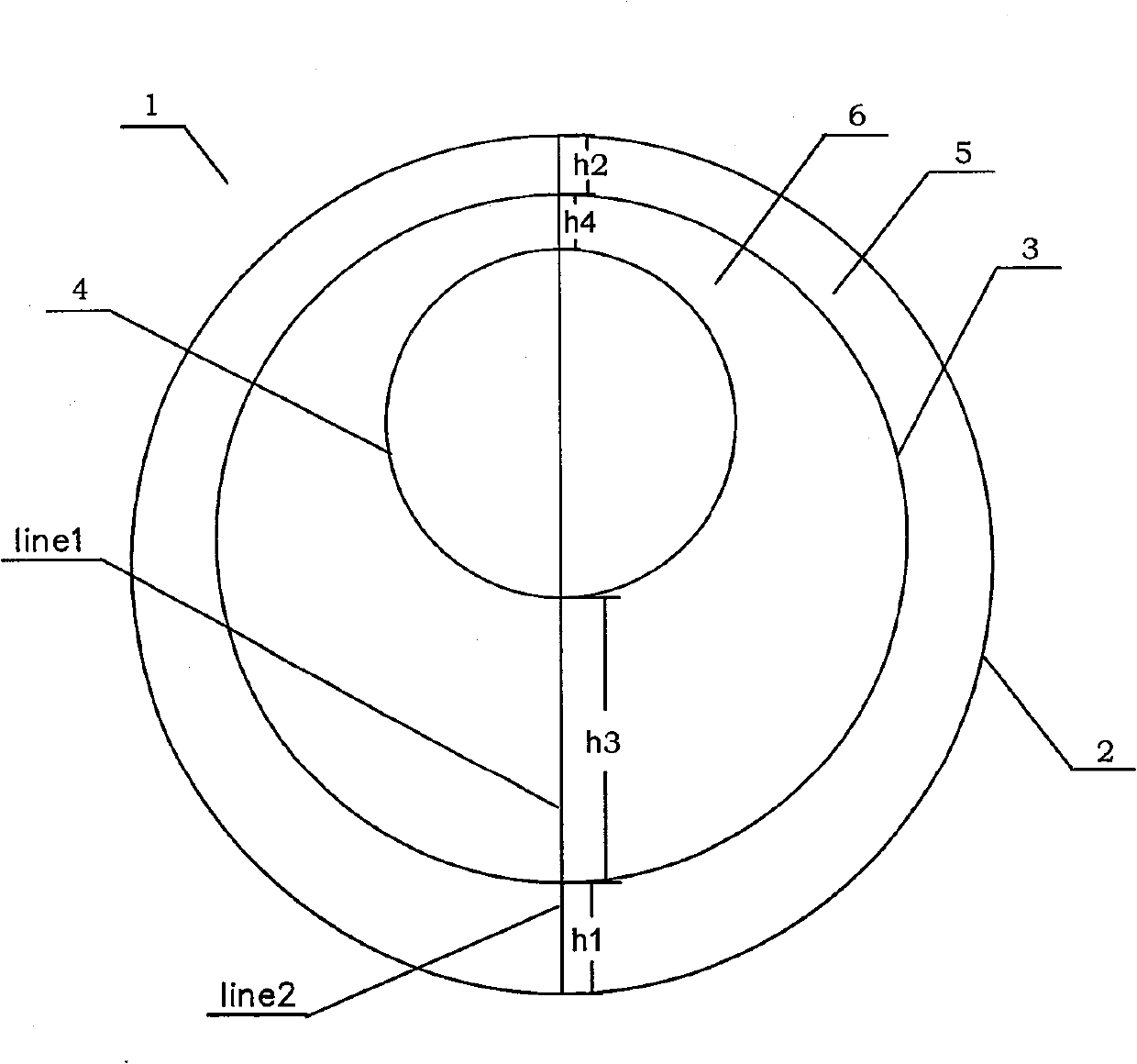
[0030] Such as figure 2 As shown, the discharge unit 1 for the ozone generator provided by Embodiment 2 of the present invention includes a ground electrode 2, an insulating layer 3 and a high-voltage electrode 4 installed in an annular phase, and the sequence from the inside to the outside is high-voltage Electrode 4, insulating layer 3 and ground electrode 2. There are gaps 5 and 6 respectively between the ground electrode 2 and the insulating layer 3 and between the high voltage electrode 4 and the insulating layer 3 . The gaps 5 and 6 in this discharge cell are uninterrupted, continuous and smooth and parallel to each other, and there is no air distribution element in the gap. The average value H2 of the gap 6 between the high voltage electrode 4 and the insulating layer 3 is 1-100 times the average value H1 of the gap 5 between the ground electrode and the insulating layer. Wherein, the average size H1=1 / 2(h1+h2) of the gap 5 between the ground electrode and the insula...


PUM

PropertyMeasurementUnit
Thicknessaaaaaaaaaa

Abstract

The invention relates to a multi-gap discharge unit for an ozone generator, which is provided with at least two discharging gaps. The discharge unit comprises a group of at least one ground electrode, an insulating barrier and a high voltage electrode which are sleeved layer by layer, the high voltage electrode and the ground electrode are separated by the insulating barrier, the gaps are arranged between the ground electrode and the insulating barrier and between the high voltage electrode and the insulating barrier and are continuously smooth and mutually parallel, the mean widths of the gaps between the ground electrode and the insulating barrier and between the high voltage electrode and the insulating barrier are 0.05mm-5mm, and the ratio of the mean width of the gap between the ground electrode and the insulating barrier to the mean width of the gap between the high voltage electrode and the insulating barrier is 1-100.

Description

Technical field: [0001] The invention belongs to the field of ozone generators and relates to a discharge unit of the ozone generator. technical background: [0002] Existing high-voltage electrodes, insulating layers and ground electrodes are installed in the discharge unit of the ozone generator, which generally includes concentrically installed high-voltage electrodes, insulating layers and ground electrodes, and most of the discharge units are high-voltage electrodes, insulating layers, and insulating layers. There is a multi-gap structure with a gap between the ground electrode and the ground electrode. However, in the existing discharge unit with multi-gap structure, there is no special limitation on the size of the two gaps, resulting in the discharge gap of the existing discharge unit being relatively large, and the relationship between the size of the two gaps is uncertain, which cannot be reasonably distributed. The amount of oxygen in the two gaps, so the ozone g...

Claims


Application Information

Patent Timeline
IPC IPC(8): C01B13/11
Inventor 陈健王涛
Owner FUJIAN NEWLAND ENTECH CO LTD
Learn More