
Target boundary imaging method for ultra-wide-band through-wall radar

A technology of through-wall radar and imaging method, which is applied in the direction of using re-radiation, radio wave reflection/re-radiation, measuring devices, etc., and can solve the problem of low calculation efficiency

Inactive Publication Date: 2012-09-26
INST OF ELECTRONICS CHINESE ACAD OF SCI
View PDF0 Cites 2 Cited by
  • Summary
  • Abstract
  • Description
  • Claims
  • Application Information

AI Technical Summary

Problems solved by technology

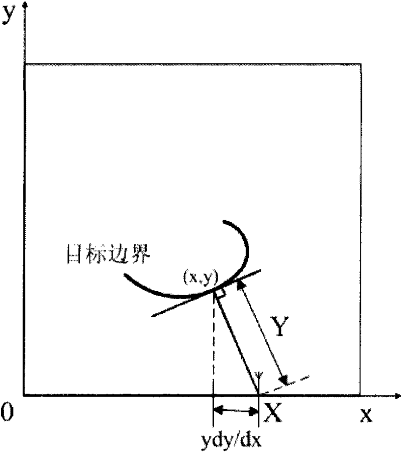
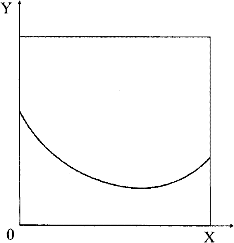
[0010] The object of the present invention is to provide a target boundary imaging method for ultra-broadband through-wall radar, to overcome the low computational efficiency in the known art through-wall imaging method,

Method used


Image

  • Target boundary imaging method for ultra-wide-band through-wall radar
  • Target boundary imaging method for ultra-wide-band through-wall radar
  • Target boundary imaging method for ultra-wide-band through-wall radar

Examples


Embodiment Construction

[0027] The present invention will be further explained in detail in conjunction with the accompanying drawings and specific embodiments.

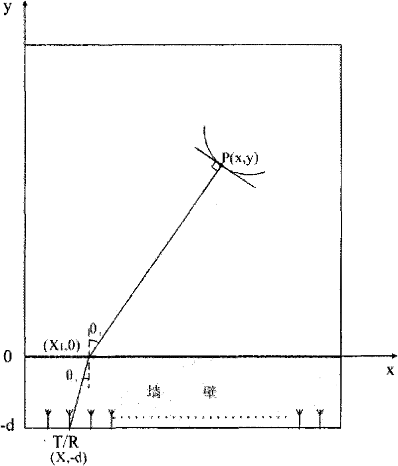
[0028] In the present invention, the transceiver multiplexing antenna array is placed close to the wall along the azimuth direction, then the target boundary imaging method described in the present invention can be applied to carry out imaging processing on the antenna array echo signal, and hide the target boundary image behind the wall (please refer to Figure 8 ).

[0029] The first step is to establish the wall model in the imaging scene of the through-wall radar target boundary, and set the system parameters required for imaging.

[0030] In the second step, the echo signal of the array antenna is input, and the input echo signal is processed by cumulative averaging and matched filtering to obtain an output signal with a high signal-to-noise ratio.

[0031] In the third step, the cubic spline function is used to fit and interpolate th...


PUM


Abstract

The invention provides a target boundary imaging method for an ultra-wide-band through-wall radar, which relates to the technology for imaging hidden target boundaries behind a wall by the ultra-wide-band through-wall radar in a limited distance. The method comprises the following steps of: establishing a wall body model in a target boundary imaging field of the through-wall radar, and setting system parameters required by imaging; inputting array antenna echo signals, and carrying out cumulative average and matching filtering processing on the input echo signals to obtain output signals withhigh signal to noise ratio; carrying out fitting interpolation calculation on the output signals obtained in the last step by using cubic spline functions, and extracting wavefront set calculation curve clusters; calculating enveloping lines of the curve clusters according to the wavefront set calculation curve clusters; and fitting the enveloping lines in the last step to obtain the target boundary images. The method takes the influence of the existence of the wall body on the propagation of electromagnetic waves into account, can realize the accurate imaging on the hidden target boundary behind the wall and has higher calculation efficiency.

Description

technical field [0001] The invention relates to an imaging method in an ultra-wideband through-wall imaging system, in particular to an ultra-wideband through-wall radar system imaging technology for hiding a target boundary behind a wall under a limited distance. Background technique [0002] Non-coherent methods and coherent methods are commonly used at home and abroad to realize ultra-wideband through-wall imaging. The non-coherent method uses the principle of Trilateration to determine the position of the target. Although the hardware is simple, it needs to solve a complex equation system, and it is difficult to solve when there are multiple targets. The coherent method generally uses the time-domain Back-Projection (BP) algorithm for imaging. This algorithm has simple hardware and high precision, but it has a large amount of calculation, it is difficult to achieve real-time processing, and the imaging effect is not satisfactory. [0003] In recent years, some scholars ...

Claims


Application Information

Patent Timeline
Patent Type & Authority Patents(China)
IPC IPC(8): G01S13/89
Inventor 黄琼陈洁孟升卫方广有
Owner INST OF ELECTRONICS CHINESE ACAD OF SCI
Learn More