Lens driving device, autofocus camera, and camera-equipped mobile terminal

A lens driving device and lens technology, which are applied to cameras, focusing devices, electromechanical devices, etc., can solve the problem of increasing the size of the lens driving device, and achieve the effect of simple optical axis alignment, reduction of defective parts and large current value.

Inactive Publication Date: 2011-03-30
SHICOH MOTOR (SHANGHAI) CO LTD
View PDF6 Cites 8 Cited by
  • Summary
  • Abstract
  • Description
  • Claims
  • Application Information

AI Technical Summary

Problems solved by technology

[0004] However, in the technology of Patent Document 1, the coil is wound into a cylinder, the center line of the cylinder is parallel to the optical axis, and the magnet is arranged at a position opposite to the end of the cylinder. There is a problem with the size of the direction becoming larger

Method used


Image

  • Lens driving device, autofocus camera, and camera-equipped mobile terminal
  • Lens driving device, autofocus camera, and camera-equipped mobile terminal
  • Lens driving device, autofocus camera, and camera-equipped mobile terminal

Examples


Embodiment Construction

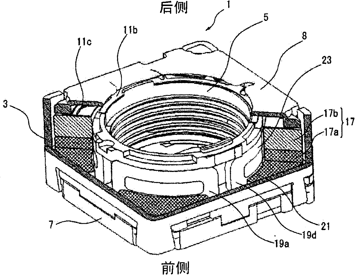
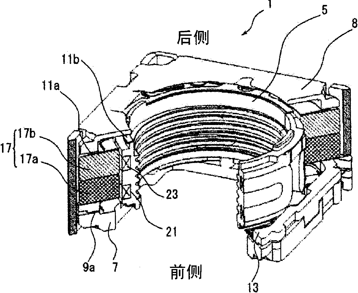
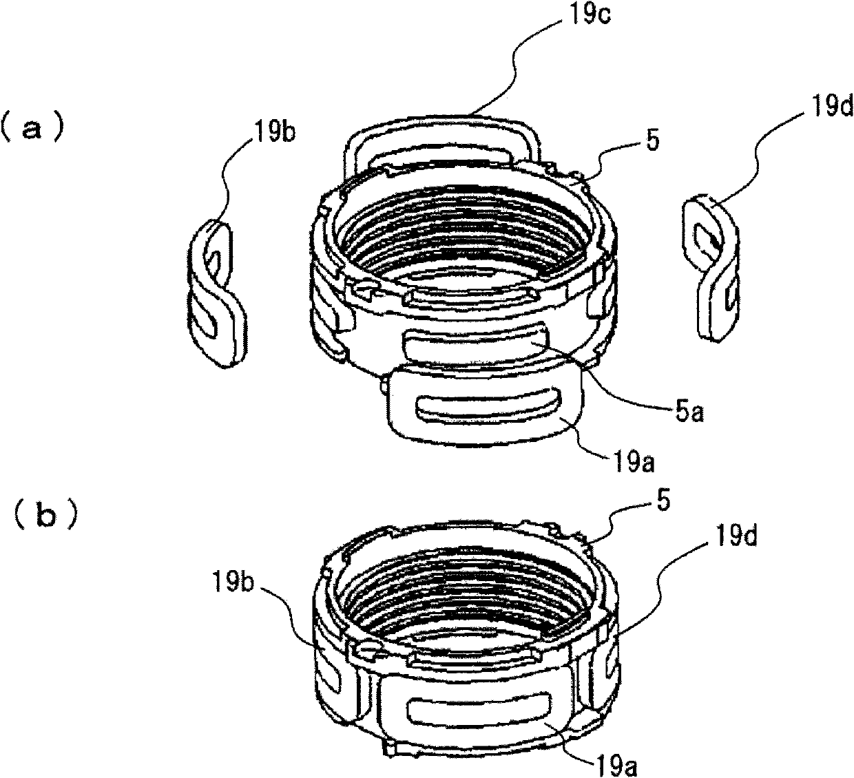
[0040] Below, please refer to the attached Figure 1 to Figure 7 , the embodiment of the present invention will be described in detail. In this embodiment, the lens driving device is a lens driving device with an auto-focus camera function incorporated into a mobile phone.

[0041] This lens driving device 1, such as Figure 5 As shown, it has an annular ring mouth 3, a lens support body 5, a frame 7 and a front side spring 9 arranged on the front side of the ring mouth 3 in the optical axis direction, a base 8 and a front side spring arranged on the rear side of the ring mouth 3. Rear side spring 11. Between the front spring 9 and the collar 3, a front spacer (insulator) 13 is arranged. A rear spacer (insulator) 15 is disposed between the rear spring 11 and the collar 3 .

[0042] The ring mouth 3 is slightly in the shape of a square tube. Magnet portions 17 are provided at four angles on the inner peripheral side of the ring mouth 3 . Each magnet portion 17 is constitu...


PUM


Abstract

A lens driving device, an autofocus camera and a camera-equipped mobile terminal are provided that can correct movement of a lens in an optical axis direction and tilt of an optical axis, and reduce the dimension thereof in the optical axis direction. The device includes: a lens support 5 for supporting a lens at an inner circumference; a plurality of coils 19a to 19d disposed at regular intervals in a circumferential direction on an outer periphery of the lens support 5; a base 8 that supports the lens support 5 so as to move freely in an optical axis direction of the lens; and a magnet portion 17 arranged on the base 8 and facing each of the coils 19a to 19d, in which an electric current of equal current value is applied to each of the coils 19a to 19d when moving the lens support 5 in the optical axis direction, and current values of the electric current applied to predetermined coils 19a to 19d are varied when correcting tilt of the optical axis of the lens.

Description

technical field [0001] The invention relates to a lens driving device, an automatic focus camera and a mobile phone with a camera function. Background technique [0002] In Patent Document 1, it is disclosed that a plurality of magnets are fixed at certain intervals in the circumferential direction of the outer periphery of a lens support body, and a frame body that supports the lens support body to move freely along the optical axis direction is provided with a position opposite to the position of the magnets. the coil. By controlling the current applied to each coil, the lens support body can be moved linearly and the lens support body can be moved obliquely to supplement the inclination angle of the optical axis. [0003] [Patent Document 1] The international publication is published in WO2008 / 128407. [0004] However, in the technology of Patent Document 1, the coil is wound into a cylinder, the center line of the cylinder is parallel to the optical axis, and the magne...

Claims


Application Information

Patent Timeline
Patent Type & Authority Applications(China)
IPC IPC(8): G03B13/36G02B7/09H02K33/18H04M1/02
CPCG02B27/0068G02B7/08
Inventor 白木学浅川聪外山宏慈
Owner SHICOH MOTOR (SHANGHAI) CO LTD
Why Eureka
Try Eureka